Aerospace & Defense RF Cable Assemblies: Standards Guide
Published on 7/27/2026 • Updated on 8/1/2026
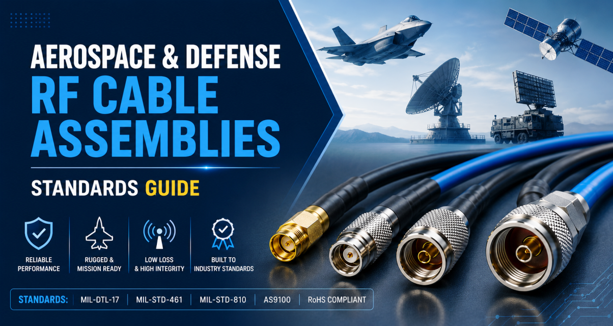
An RF cable assembly that works fine on a lab bench can fail on an airframe, in a satellite, or on a missile guidance system. Not because commercial parts are badly made, but because "acceptable" on the ground and "acceptable" at 40,000 feet in a shaker table at 55 °C are different definitions of the word. Aerospace and defense RF cable assemblies are engineered to close that gap.
The result is a set of standards, materials, workmanship rules, tests, and paperwork that turns a functional interconnect into a certified component. This guide walks through what those standards actually require, what changes on the factory floor, and how to know whether your project truly needs mil-spec assemblies or whether commercial parts will do the job.
On This Page
- Why Aerospace and Defense RF Is Different
- The Cable Itself: MIL-DTL-17 Explained
- The Connectors: MIL-PRF-39012 and MIL-STD-348
- Workmanship: IPC Class 3 and NASA-STD-8739.3
- Handling, Cleanliness, and ESD Control
- Marking and Identification
- Testing: Where the Cost Actually Lives
- Space-Specific Requirements
- Documentation and Traceability
- Commercial vs Military at a Glance
- When You Actually Need Aerospace Grade
- Common Specification Mistakes
- Frequently Asked Questions
- Bottom Line
Why Aerospace and Defense RF Is Different
The environment is the first reason. A commercial cable is qualified for 0 to +70 °C, maybe -40 to +85 °C on the good end. Aerospace RF regularly sees -55 °C in a wing bay at altitude and +200 °C or higher on an engine-nacelle harness. That single fact ripples through every material choice: dielectrics, jackets, plating, adhesives, potting compounds. PVC does not survive; PTFE and FEP do.
The second reason is what "acceptable failure rate" means. On a commercial radio link, a rare intermittent is annoying. On a fighter-jet radar, an intermittent is a false target. On a satellite downlink, it is a mission lost. On a missile, it is worse. That drives every process decision downstream: 100 percent electrical screening instead of AQL sampling, IPC Class 3 solder joints instead of Class 2, full lot traceability instead of a part number and a date code.
The Cable Itself: MIL-DTL-17 Explained
MIL-DTL-17 (formerly MIL-C-17) is the governing military standard for RF coaxial cable. If you see cable specified as "MIL-17" or listed by an "RG-" number followed by an "/U" designation, you are looking at this standard. It defines materials, construction, dimensions, electrical performance, and test methods for every cable type in the family.
The key material differences from commercial cable:
Center conductor
Silver-plated copper or silver-plated copper-clad steel. Silver keeps RF loss down at high frequencies and holds contact resistance stable over decades.
Dielectric
Solid or low-density PTFE. Stable across -55 to +200 °C, low RF loss, dimensional stability across the operating range.
Shield
Silver-plated copper braid, often double or triple, sometimes with foil layers. Coverage is typically 90 to 96 percent or better versus 70 to 90 percent for commercial single-braid.
Jacket
FEP, PFA, or PTFE. Rated to +200 °C or higher (+260 °C for some variants), resistant to fuels, hydraulic fluids, and de-icing agents.
Shielding effectiveness for MIL-DTL-17 cable typically clears 100 dB and can exceed 130 dB on double-shielded or semi-rigid constructions. That matters in avionics bays where dozens of RF systems share a small volume and any radiated coupling becomes an EMI problem someone else has to solve.
Semi-rigid options: aerospace phased-array radars, satellite payloads, and precision test equipment routinely use semi-rigid cable in standard diameters of 0.085", 0.141" and 0.250". The solid copper (sometimes tin-plated) outer conductor gives shielding above 130 dB and phase stability better than any flexible construction. The trade-off is that once formed, the shape is essentially permanent. Conformable variants exist for cases where hand-forming and some limited rework are needed.
The Connectors: MIL-PRF-39012 and MIL-STD-348
MIL-PRF-39012 is the performance specification for RF coaxial connectors used in military applications. It defines materials, plating specifications, environmental performance, and lot traceability. MIL-STD-348 is the interface dimensional standard that MIL-PRF-39012 references. Together they define what a military-grade SMA, N-Type, TNC, BNC, or LEMO connector actually has to do.
Here is what surprises people: a commercial SMA and a MIL-PRF-39012 SMA can look identical. They can even fit and mate. But they are not the same part.
Controlled plating thickness
Gold and silver plating thicknesses are specified in the drawing and verified. Nickel underplating is controlled to prevent long-term diffusion that would degrade RF performance.
Environmental qualification
Every listed part number has been vibration-tested, thermal-cycled, salt-fog-tested, and mated thousands of times before its qualification report was signed.
Lot traceability
Every connector ties back to a specific manufacturing lot with material certifications and process records. If a failure surfaces three years from now, the paperwork lets you trace it back.
Passivation and finish
Stainless-steel shells are passivated per AMS 2700 or equivalent. Aluminum housings receive controlled anodizing. These are not cosmetic; they define long-term corrosion behavior.
Workmanship: IPC Class 3 and NASA-STD-8739.3
This is where the biggest hidden cost hides. The soldering, crimping, and cable-preparation standards for aerospace and defense are stricter than anything a commercial line runs to.
The applicable standards are IPC J-STD-001 Class 3 (soldering requirements for high-reliability electronics) and IPC/WHMA-A-620 Class 3 (requirements for cable and wire harness assemblies). For NASA and space work, add NASA-STD-8739.3 for hand soldering. Every operator on the line must be trained and certified against these standards. Recertification is periodic.
What Class 3 actually requires on an RF cable termination:
- ✓ 100 percent wetting of the center conductor and shield braid, verifiable under magnification
- ✓ Minimum 75 percent solder fill in the connector barrel
- ✓ Zero nicked or scraped strands during preparation
- ✓ No burns, melting, or thermal damage to insulation
- ✓ Controlled solder fillet geometry to prevent impedance discontinuities
- ✓ Certified solder alloy (Sn63/Pb37 or a program-approved lead-free equivalent)
- ✓ Complete flux residue removal, verified by ionic contamination testing where required
Commercial Class 2 workmanship is fine on a router pigtail. On a fighter-jet radar interconnect, a solder joint that meets Class 2 but not Class 3 can pass initial electrical test and then fail six months later after a few dozen thermal cycles. That is the failure mode Class 3 is designed to eliminate.
Handling, Cleanliness, and ESD Control
Aerospace assembly floors are not commercial floors. Depending on the program, the differences include:
- Documented ESD control zones with grounded work surfaces, wrist straps, and periodic verification
- Particulate control (sometimes cleanroom-class for space-grade work)
- Gloves or finger cots to prevent contamination of plating and dielectric surfaces
- Sealed, labeled packaging with desiccant for materials in inventory
- First-article inspection per AS9102 for aerospace programs
- Written work instructions for every operation, with in-process verification and inspection sign-offs
- No unauthorized rework: once a semi-rigid is formed, it is not re-bent; once a solder joint is made and inspected, it is not touched again without a formal rework authorization
These process controls do not show up in the finished product's photograph. They show up in the failure rate two years after delivery.
Marking and Identification
Every aerospace or defense RF assembly carries permanent identifying marks that survive the full environmental range. Typical requirements:
| Marking | Purpose |
|---|---|
| Part or Identifying Number (PIN) | Per MIL-DTL-17 or the customer drawing |
| Manufacturer's CAGE code | Identifies the manufacturer to DoD systems |
| Date code or lot number | Ties the assembly to its manufacturing lot |
| Serial number | Individual traceability for high-criticality assemblies |
| Contract or program identifier | Required by some contracts |
Marking methods (laser, thermal ink, heat stamp) must not damage the jacket or alter electrical performance. For space-grade hardware, marking materials must be non-outgassing per ASTM E595 and must not create particulate contamination.
Aerospace and Defense Cable Assemblies
SigmaRF builds mil-spec RF cable assemblies to MIL-DTL-17 cable and MIL-PRF-39012 connectors, with IPC/WHMA-A-620 Class 3 workmanship and full test data packages. Semi-rigid, conformable, and phase-stable flexible options across the frequency range.
Request a Quote →Testing: Where the Cost Actually Lives
Commercial RF assemblies are typically tested for VSWR, insertion loss, and continuity on a sample basis. Aerospace and defense assemblies are usually 100 percent screened on the electrical tests and lot-sampled on the environmental tests. This is where most of the cost gap lives.
Electrical tests (often 100 percent)
- ✓ Insertion loss across the full operating band
- ✓ VSWR or return loss to the specified limits
- ✓ Continuity and DC resistance
- ✓ Insulation resistance
- ✓ Dielectric withstanding voltage (DWV)
- ✓ Shielding effectiveness where specified
- ✓ Time-domain reflectometry (TDR) to catch impedance discontinuities that VSWR alone might miss
- ✓ Phase matching for multi-channel or phased-array sets
Mechanical and environmental tests (qualification and lot sampling)
- ● Vibration per MIL-STD-810 (sine and random profiles)
- ● Mechanical shock
- ● Thermal cycling (often -55 to +125 °C, wider for extreme programs)
- ● Thermal shock (rapid temperature transitions)
- ● Humidity and moisture resistance
- ● Salt fog and corrosion
- ● Fluid immersion (jet fuel, hydraulic fluid, de-icing fluid)
- ● Altitude and low-pressure exposure
- ● Flexure life for flexible designs
- ● Bend radius verification
Qualification typically follows a formal test plan with Group A (100 percent electrical), Group B (sample mechanical and environmental), and Group C (periodic design verification) categories. For fully qualified RF cable assemblies, the governing standard is often MIL-DTL-87104.
Space-Specific Requirements
Space adds another layer above and beyond aerospace. Vacuum, cosmic radiation, extreme thermal cycling, and the impossibility of on-orbit repair mean the requirements get stricter still. Standards commonly invoked include ESCC 3408 (European Space Agency) and various NASA specifications.
Thermal vacuum testing
Assembly is thermal-cycled in a vacuum chamber to simulate the launch and orbit environment. Confirms that materials do not release volatiles under low pressure and that solder joints hold up under the combined stress.
Outgassing per ASTM E595
Every material in the assembly must meet Total Mass Loss (TML) below 1 percent and Collected Volatile Condensable Materials (CVCM) below 0.1 percent. Contamination on optical surfaces from outgassed volatiles has ended missions.
Radiation hardness
Total Ionizing Dose (TID) characterization and, for certain programs, Single Event Effect (SEE) evaluation. Passive RF hardware is more robust than active electronics but is not immune, especially for long missions or high-radiation orbits.
Particle Impact Noise Detection (PIND)
The assembly is vibrated while an acoustic sensor listens for loose particles inside sealed components. Zero-particle tolerance for spaceflight.
Documentation and Traceability
Every aerospace or defense RF cable assembly ships with a paper trail. If a failure surfaces in the field five years later, this documentation is how the investigation reconstructs what happened.
- ● Certificate of Conformance (CoC) stating compliance with the governing specifications
- ● Material certifications for cable, connectors, and solder
- ● Lot traceability records tying every part to its manufacturing lot
- ● Full test data package with actual measured insertion loss, VSWR, TDR traces, and other required data
- ● First-article inspection reports per AS9102 when the contract requires them
- ● Process records including operator ID, solder alloy lot, torque values, cleaning verification
- ● Failure analysis support capability when required
This is what commercial RF cable assemblies almost never carry, and it is a significant part of what you are paying for.
Commercial vs Military at a Glance
| Attribute | Commercial | Aerospace / Defense |
|---|---|---|
| Cable spec | Manufacturer catalog | MIL-DTL-17 |
| Connector spec | Manufacturer catalog | MIL-PRF-39012, MIL-STD-348 |
| Temperature | -40 to +85 °C typical | -55 to +200 °C (up to +260 °C) |
| Dielectric | PE or foam PE | PTFE |
| Jacket | PVC or PE | FEP, PFA, or PTFE |
| Center conductor | Bare or tinned copper | Silver-plated copper (or SPC-clad steel) |
| Shield coverage | 70 to 90 percent | 90 to 96+ percent, often multi-layer |
| Workmanship | IPC Class 2 or manufacturer standard | IPC J-STD-001 Class 3, IPC/WHMA-A-620 Class 3 |
| Electrical test | Sample or lot-based | 100 percent screening |
| Environmental test | Rare | MIL-STD-810 or program-specific |
| Traceability | Part number and date code | Full material, lot, and process records |
| Documentation | Basic datasheet | CoC, material certs, full test data |
| Relative cost | Baseline | 5 to 20 times higher |
When You Actually Need Aerospace Grade
Not every project on an aerospace program needs full MIL-spec assemblies. Ground test benches, engineering prototypes, and non-flight hardware often do fine with commercial or lightly-uprated parts. Real mil-spec is warranted when:
Use aerospace/defense grade when
- ✓ The assembly flies (aircraft, missile, satellite, launch vehicle)
- ✓ The contract explicitly requires MIL-DTL-17 or MIL-PRF-39012 parts
- ✓ Environmental extremes are involved (temperature, vibration, altitude, fluids)
- ✓ Service life exceeds 10 years without maintenance access
- ✓ Failure has mission-critical or safety-of-flight consequences
- ✓ Full traceability is required by the customer or the certification authority
Commercial is likely enough when
- ✓ Ground-support equipment (GSE) in a lab or hangar
- ✓ Engineering prototype and integration test articles
- ✓ Non-flight bench measurement setups
- ✓ Training and simulation rigs
- ✓ Short-life or expendable hardware where cost drives the decision
Common Specification Mistakes
- ✗ Specifying "MIL-spec" without naming the actual standard. MIL-DTL-17 is the cable, MIL-PRF-39012 is the connector, MIL-DTL-87104 is the finished assembly. They are not interchangeable.
- ✗ Ordering commercial connectors and expecting them to hold up in a MIL-DTL-17 assembly. The cable can be mil-spec; the connector is a separate qualification.
- ✗ Skipping the workmanship standard because "it's just a solder joint." IPC Class 3 versus Class 2 is exactly where latent field failures come from.
- ✗ Not budgeting for the test data package. On a full-spec build, testing and documentation can be 30 to 50 percent of the price.
- ✗ Buying space-grade when only aerospace-grade is required. The outgassing and radiation certifications add substantial cost that ground and airborne systems do not need.
- ✗ Assuming a commercial part that "meets all the same performance numbers" is a substitute. Performance is only one axis; process control, traceability, and qualification testing are the rest.
- ✗ Reworking a semi-rigid cable in the field after it was formed at the factory. Not permitted under most mil-spec workmanship standards.
Frequently Asked Questions
What is MIL-DTL-17?
MIL-DTL-17 is the U.S. military detail specification for RF coaxial cables. Formerly known as MIL-C-17, it defines the materials, construction, dimensions, electrical performance, and test methods for cables used in military and aerospace applications. If a cable is called "RG-142/U" or "M17/60-RG142," it is built to MIL-DTL-17.
What is MIL-PRF-39012?
MIL-PRF-39012 is the U.S. military performance specification for RF coaxial connectors. It covers general performance, materials, plating, environmental qualification, and lot traceability requirements. It cross-references MIL-STD-348 for interface dimensions. Together they define what a qualified military-grade SMA, N-Type, TNC, or BNC connector must deliver.
What is IPC Class 3 workmanship?
IPC Class 3 is the highest workmanship classification in IPC J-STD-001 (soldering) and IPC/WHMA-A-620 (cable and wire harness assembly). It is used for products where continued performance and life are critical, and where the product cannot tolerate downtime. Aerospace, defense, medical implant, and some automotive-safety systems all specify Class 3. The requirements cover solder wetting, fillet geometry, absence of damage, and inspection criteria at magnification.
What is MIL-STD-810?
MIL-STD-810 is the U.S. military standard for environmental engineering test methods. It defines how to test hardware for vibration, mechanical shock, thermal cycling, humidity, altitude, salt fog, and dozens of other environmental conditions. Aerospace RF cable assemblies are commonly qualified against selected MIL-STD-810 methods appropriate to their intended use.
What is NASA-STD-8739.3?
NASA-STD-8739.3 is the NASA technical standard for soldered electrical connections. It defines materials, processes, workmanship, and operator certification for hand-soldered joints on spaceflight hardware. For NASA and space-related programs, it often applies in addition to (or in place of) IPC J-STD-001.
What is ASTM E595 outgassing?
ASTM E595 is the standard test method for measuring outgassing from materials in a vacuum environment. It reports Total Mass Loss (TML) and Collected Volatile Condensable Materials (CVCM). Space-grade RF cable assemblies use materials with TML below 1 percent and CVCM below 0.1 percent to avoid contaminating optical or thermal-control surfaces on spacecraft.
How much more do aerospace RF cable assemblies cost?
Depending on the specification, aerospace and defense RF cable assemblies typically cost 5 to 20 times more than commercial equivalents. Space-grade assemblies with full radiation and outgassing certification can cost significantly more. The premium is not markup; it covers premium materials, IPC Class 3 workmanship, 100 percent electrical testing, environmental qualification testing, and full documentation and traceability.
What is the difference between aerospace and space grade?
Aerospace grade means qualified for airborne use (aircraft, missiles) under environments defined by MIL-STD-810 or similar. Space grade adds requirements for vacuum, radiation, and outgassing that aerospace parts do not have to meet. All space-grade parts are aerospace-grade, but not the reverse. Specifying space when aerospace is enough is a common budget mistake.
Do I need MIL-DTL-17 cable if my program doesn't require it?
If the contract or the certification authority does not require it, then no. Commercial and industrial-grade RF cable can be entirely adequate for ground-support equipment, test benches, and non-flight hardware. Save mil-spec for what actually flies or lives in a truly extreme environment.
What is a CAGE code?
A CAGE (Commercial and Government Entity) code is a five-character identifier issued by the U.S. Defense Logistics Agency to identify manufacturers and suppliers to the Department of Defense. Aerospace and defense RF cable assemblies must be marked with the manufacturer's CAGE code for traceability.
Bottom Line
The gap between a commercial RF cable assembly and an aerospace or defense one is not the datasheet performance. Both can hit the same VSWR and insertion loss numbers on the bench. The gap is in what happens after the bench: what the materials survive, how the joints hold up after a thousand thermal cycles, whether a failure three years from now can be traced back to a specific lot and operator.
The standards (MIL-DTL-17 for cable, MIL-PRF-39012 for connectors, IPC Class 3 for workmanship, MIL-STD-810 for environmental testing, MIL-DTL-87104 for finished assemblies, plus the space additions when applicable) exist because that gap has been paid for in real failures, real lost missions, and real lives. When your program has to fly or launch, matching parts to those standards is not optional. When it does not, commercial parts save a lot of money without any real risk.
Match the assembly to the mission. That is the only rule that never changes.
Aerospace and Defense RF Cable Assemblies from SigmaRF
MIL-DTL-17 cable, MIL-PRF-39012 connectors, IPC/WHMA-A-620 Class 3 workmanship, full electrical screening and test data packages. Semi-rigid and flexible constructions across the frequency range, with the documentation your certification authority expects.
Request a Quote Talk to an Engineer- Why Cheap RF Cable Assemblies Fail: Construction Shortcuts and How to Spot Them
- Solving Antenna Range Loss on an IoT Device: A Worked Diagnostic Example
- SMA Mating Cycles: How Many Connections Can an SMA Survive?
- RG58 Attenuation: Datasheet Specs vs Real-World Loss
- VNA Testing for Cable Assemblies: How VSWR and Insertion Loss Verification Works
- How a Custom Coaxial Cable Assembly Is Built, Step by Step
- Cellular Repeater and DAS Cable Selection: In-Building Coverage Guide
- Wi-Fi HaLow (802.11ah): Sub-GHz Wi-Fi and Its Antenna/Cable Needs
- RF Interconnects for Test Labs: Building a Reliable VNA Bench
- Direct-to-Cell Satellite and IoT: What It Means for Ground Hardware