What is the main difference between coaxial cable and waveguide?
Published on 7/31/2026 • Updated on 8/1/2026
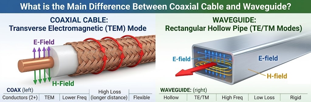
The short version that every RF engineer carries around: coax is broadband, compact, flexible, and cheap; waveguide is low-loss, high-power, and physically large. Coax wins by default in most systems. Waveguide wins decisively in the specific places where its advantages are worth its bulk: high-power radar transmitters, satellite ground station feeds, and millimeter-wave systems where coax loss becomes unbearable.
This article explains why, at a level useful both to engineering students meeting the topic for the first time and to working engineers who want the practical numbers in one place. We'll cover the physics of how each line guides energy, the cutoff frequency concept that defines waveguide behavior, real loss and power-handling numbers, the WR sizing system, and a decision framework you can actually use.
On This Page
- How Coaxial Cable Guides Energy: The TEM Mode
- How Waveguide Guides Energy: TE and TM Modes
- Cutoff Frequency: The Number That Defines Waveguide
- Worked Example: WR-90 Cutoff and Operating Band
- The WR Designation System
- Loss: The Comparison That Decides Most Systems
- Power Handling
- Bandwidth and Dispersion
- Size, Weight, Flexibility, and Cost
- Head-to-Head Comparison Table
- Who Uses What, and Why
- Hybrid Systems: Where Coax and Waveguide Meet
- The Decision Framework
- Frequently Asked Questions
- Bottom Line
How Coaxial Cable Guides Energy: The TEM Mode
A coaxial cable is two conductors: a center conductor and a surrounding outer conductor, separated by a dielectric. The RF energy travels in the electromagnetic field between the two conductors, not "inside the wire" as intuition suggests. The electric field points radially from center conductor to shield; the magnetic field circles the center conductor; and both are entirely transverse (perpendicular) to the direction of travel.
This field configuration is called the TEM mode (Transverse ElectroMagnetic), and it has a property that makes coax uniquely useful: it works at every frequency from DC upward. There is no minimum frequency. The same piece of coax that carries a DC bias voltage also carries a 6 GHz signal, simultaneously if you want. This is why bias-tees, DC-coupled instrumentation, and broadband systems are all built on coax.
Coax does have an upper frequency limit, and understanding it sets up the whole comparison. When the operating wavelength becomes comparable to the cable's circumference, the cable can start supporting additional field configurations (higher-order modes) beyond TEM. Multiple modes traveling at different velocities corrupt the signal. The practical consequence: higher frequencies demand physically smaller coax. That is why precision 1.85 mm connectors reach 67 GHz while big 7/16 DIN connectors stop around 7.5 GHz. And smaller coax means a smaller center conductor, which means more conductor loss. That spiral (higher frequency, smaller cable, more loss) is exactly the problem waveguide exists to escape.
How Waveguide Guides Energy: TE and TM Modes
A rectangular waveguide is, structurally, almost nothing: a hollow metal pipe, usually rectangular in cross-section, filled with air. No center conductor. No dielectric. The RF energy propagates as an electromagnetic wave bouncing down the inside of the pipe, confined by the conducting walls.
Without two conductors, the TEM mode cannot exist. Instead, waveguide supports TE modes (Transverse Electric: the electric field is transverse, but the magnetic field has a component along the direction of travel) and TM modes (Transverse Magnetic: the reverse). The workhorse is the TE₁₀ mode, the fundamental mode of rectangular waveguide, where the electric field spans the narrow dimension of the guide and varies as a half sine across the broad dimension.
Removing the center conductor is where all of waveguide's famous advantages come from:
- Dramatically lower loss. The dominant loss mechanism in coax (skin-effect resistance in the small center conductor) is simply gone. Current flows only in the large-area inner walls of the guide.
- No dielectric loss. The guide is air-filled. There is no polyethylene or PTFE absorbing RF energy.
- Enormous power handling. Breakdown is limited by the air gap across the full guide dimension, not the sub-millimeter gap in a coax dielectric.
- Perfect shielding. The energy is enclosed by a continuous metal pipe. Nothing leaks.
The price is equally fundamental: a hollow pipe only guides waves whose wavelength fits inside it. That constraint is the cutoff frequency, and it deserves its own section.
Cutoff Frequency: The Number That Defines Waveguide
A waveguide behaves as a high-pass structure. Below a specific frequency, the cutoff frequency, the wave physically cannot propagate down the guide; it decays exponentially within a short distance instead. Above cutoff, it propagates with very low loss. This is the single biggest conceptual difference from coax, which passes everything from DC up.
For the TE₁₀ mode in a rectangular waveguide, the cutoff depends only on the broad interior dimension of the guide:
TE₁₀ cutoff frequency
where:
f_c = cutoff frequency (Hz)
c = speed of light (3 × 10⁸ m/s)
a = broad interior dimension of the guide (m)
Two practical consequences follow immediately. First, lower frequencies need bigger pipes: a waveguide for 1 GHz would need a broad dimension of about 15 cm, which is why nobody runs waveguide at VHF. Second, each waveguide size has a usable band, conventionally from about 1.25 × f_c (where loss and dispersion near cutoff have settled down) to about 1.9 × f_c (below the point where the next mode, TE₂₀, can start propagating and corrupt the signal). Roughly one octave of clean single-mode bandwidth per guide size.
Worked Example: WR-90 Cutoff and Operating Band
WR-90 is the standard X-band waveguide, and the "90" tells you its broad dimension: 0.90 inches (22.86 mm). Let's compute its behavior.
WR-90 calculation
f_c = (3 × 10⁸) / (2 × 0.02286)
f_c = 6.557 GHz
Recommended band:
lower ≈ 1.25 × 6.557 = 8.2 GHz
upper ≈ 1.9 × 6.557 = 12.4 GHz
And indeed, the published operating band of WR-90 is 8.2 to 12.4 GHz, which is the X-band used by weather radar, marine radar, and many military systems. The formula is not an approximation of the datasheet; the datasheet is an application of the formula. Every WR size works the same way, which is why an RF engineer can estimate any waveguide's band from its number alone.
The WR Designation System
Rectangular waveguide sizes are standardized under the EIA "WR" (Waveguide, Rectangular) system, where the number is the broad interior dimension in hundredths of an inch. The sizes an engineer most often meets:
| Designation | Operating Band | Band Name | Typical Applications |
|---|---|---|---|
| WR-284 | 2.6 to 3.95 GHz | S-band | Air traffic control radar, weather radar |
| WR-137 | 5.85 to 8.2 GHz | C-band | Satellite uplinks, microwave links |
| WR-90 | 8.2 to 12.4 GHz | X-band | Marine and weather radar, defense |
| WR-62 | 12.4 to 18 GHz | Ku-band | Satellite TV, VSAT terminals |
| WR-42 | 18 to 26.5 GHz | K-band | Point-to-point links, radar |
| WR-28 | 26.5 to 40 GHz | Ka-band | 5G backhaul, satellite, automotive radar test |
| WR-10 | 75 to 110 GHz | W-band | Automotive radar (77 GHz), imaging, research |
Notice the trend: as frequency rises, the guide shrinks. WR-284 is a substantial metal duct nearly 3 inches wide; WR-10 is a precision channel one-tenth of an inch across. At the low end, waveguide is impractically bulky. At the very high end (above roughly 60 GHz), waveguide becomes not just competitive with coax but often the only sensible choice, because coax loss at those frequencies is punishing.
Loss: The Comparison That Decides Most Systems
Here is the comparison in numbers, at 10 GHz, for representative transmission lines:
| Transmission Line | Typical Loss @ 10 GHz | Loss Over a 10 m Run |
|---|---|---|
| Flexible coax (RG-402 class) | ~0.8 to 1.5 dB/m | 8 to 15 dB (mostly gone) |
| Premium low-loss coax | ~0.5 to 0.8 dB/m | 5 to 8 dB (badly hurt) |
| WR-90 waveguide (copper) | ~0.1 dB/m | ~1 dB (fine) |
The gap is roughly an order of magnitude, and it comes straight from the physics: waveguide has no center conductor concentrating current into a thin, high-resistance surface, and no dielectric absorbing energy. Wall currents flow over the guide's large interior surface area at low current density.
The gap widens with frequency. At 77 GHz, even the best small coax runs several dB per meter, while WR-10 waveguide runs a fraction of that. This is why mmWave test benches, automotive radar test systems, and radio astronomy receivers are plumbed in waveguide even for short interconnects: at those frequencies, every centimeter of coax costs real signal.
On a receive path, this loss difference translates directly to system noise figure. A satellite ground station with a 10 m feed run cannot afford 8 dB of coax loss between the antenna and the LNA. Waveguide (or moving the LNA to the antenna) is not optional there; it is the design.
Power Handling
Two mechanisms limit how much power a transmission line carries: average power (heat: the line's losses turn signal into temperature, and materials have limits) and peak power (voltage breakdown: arc-over across the dielectric or air gap).
Waveguide dominates both. Its lower loss means less self-heating per watt carried, its all-metal construction sheds heat well, and its breakdown gap is the full guide dimension of air rather than a millimeter or two of solid dielectric. Representative numbers at X-band:
| Line | Average Power @ 10 GHz | Peak Power |
|---|---|---|
| 0.141" semi-rigid coax | ~50 to 100 W | A few kW |
| WR-90 waveguide | Kilowatts continuous | ~1 MW class (sea level, dry air) |
This is why every high-power radar transmitter, broadcast klystron, industrial microwave heating system, and particle accelerator RF chain in the world routes its power through waveguide. There is no coax alternative at megawatt peak powers. Pressurizing the guide with dry air or SF6 raises the breakdown threshold further, a standard trick in high-power radar.
Bandwidth and Dispersion
Here coax strikes back, on two counts.
Bandwidth. A single coax line covers DC to tens of GHz continuously. A single waveguide size covers roughly one octave. A broadband system spanning 2 to 18 GHz runs on one coax cable, or on four different waveguide sizes with transitions between them. For instrumentation, EW receivers, and any wideband application, that is decisive.
Dispersion. In coax's TEM mode, all frequencies travel at (nearly) the same velocity, so wideband signals hold their shape. In waveguide, propagation velocity depends on how far above cutoff you are: frequencies near cutoff travel slower than frequencies well above it. A wideband pulse sent down a long waveguide spreads and distorts. Radar system designers know this and account for it; it is manageable, but it is a real effect that TEM lines simply do not have.
Size, Weight, Flexibility, and Cost
The practical, unglamorous factors decide as many designs as the electrical ones.
- Routing. Coax bends around corners, coils for storage, and threads through cable trays. Rectangular waveguide changes direction only through machined E-bends, H-bends, and twists, each a purchased precision component. Flexible waveguide exists (corrugated wall construction) but is expensive, lossy compared to rigid guide, and used sparingly for final alignment rather than general routing.
- Weight. A WR-284 run is heavy metal ductwork requiring hangers and support structure. Coax hangs from cable ties.
- Installation skill. Coax terminates with connectors installed in minutes. Waveguide joins with flanges (choke or cover type) that must be flat, clean, correctly gasketed, and evenly torqued; a poor flange joint leaks RF and creates reflections. Pressurized systems add leak testing.
- Cost. Coax assemblies are inexpensive to moderate. Waveguide components (straight sections, bends, twists, transitions, flexible sections) are machined precision hardware, each priced accordingly. A waveguide run costs an order of magnitude more per meter than a coax run, before installation labor.
The Coax Side, Built Right
Most systems, even waveguide-fed ones, run on coax everywhere else: instrument connections, LNA outputs, IF paths, test benches. SigmaRF builds those assemblies in RG, LMR, and semi-rigid constructions to 40 GHz and beyond, each individually VNA-swept for VSWR and insertion loss before shipment.
Get a Custom Assembly →Head-to-Head Comparison Table
| Property | Coaxial Cable | Rectangular Waveguide |
|---|---|---|
| Propagation mode | TEM | TE₁₀ (fundamental), TE/TM family |
| Frequency range | DC to upper mode limit (broadband) | ~One octave above cutoff (bandpass) |
| Loss @ 10 GHz | 0.5 to 1.5 dB/m | ~0.1 dB/m |
| Peak power @ X-band | Kilowatt class | Megawatt class |
| Carries DC | Yes | No |
| Dispersion | Essentially none (TEM) | Significant near cutoff |
| Flexibility | Flexible to semi-rigid | Rigid; machined bends and twists |
| Size and weight | Compact, light | Bulky, heavy (worse at low frequency) |
| Cost per meter | Low to moderate | High (precision machined hardware) |
| Shielding | 60 to 140 dB by construction | Essentially perfect (enclosed pipe) |
Who Uses What, and Why
| Application | Choice | Driving Reason |
|---|---|---|
| Cellular / Wi-Fi infrastructure | Coax | Sub-6 GHz, moderate power, routing flexibility, cost |
| Test benches and instruments | Coax (to ~50 GHz) | Broadband, reconfigurable, DC-coupled |
| High-power radar transmitter | Waveguide | Megawatt peak power, no coax alternative |
| Satellite ground station feed | Waveguide | Long run + noise figure budget rules out coax loss |
| Satellite payload internals | Both | Waveguide for high-power output, semi-rigid coax elsewhere |
| mmWave test (60 to 110 GHz) | Waveguide | Coax loss at W-band is prohibitive |
| Broadcast transmitter feed | Waveguide or rigid coax | Power and loss over long tower runs |
| Consumer and IoT devices | Coax | Size, cost, and flexibility dominate entirely |
Hybrid Systems: Where Coax and Waveguide Meet
Real systems rarely choose one or the other exclusively. A typical satellite ground station illustrates the standard pattern: the high-power amplifier output travels through waveguide to the antenna feed (power and loss dictate it), while the receive-side LNA output, the up/down converter connections, the reference signals, and the entire equipment room run on coax (bandwidth, flexibility, and cost dictate that).
The component that stitches the two domains together is the coax-to-waveguide transition (also called a waveguide launcher or adapter). The most common design inserts the coax center conductor as a small probe through the guide's broad wall, a quarter guide-wavelength from a shorted back wall; the probe couples the coax's TEM field into the guide's TE₁₀ field. A well-made transition achieves better than 20 dB return loss across the guide's band with a few tenths of a dB of insertion loss. Every waveguide test setup you will ever see has these on the instrument ends, because the VNA's ports are coax.
So the working engineer's relationship with this topic is rarely "choose one." It is "know where the boundary belongs in this system, and spec a good transition at the boundary."
The Decision Framework
Four questions, asked in order, settle nearly every case:
Question 01
Is peak or average power beyond coax territory?
Above a few kilowatts peak at microwave frequencies, waveguide is not a preference, it is the only option. Decision made.
Question 02
Does the loss budget survive coax over this run at this frequency?
Compute it: length × dB/m at your frequency. If the answer eats your link margin or your noise figure, waveguide (or relocating the electronics to shorten the run) is the fix. This is the question that puts waveguide into ground stations and mmWave benches.
Question 03
Do you need bandwidth wider than one octave, or DC continuity?
If yes to either, coax. A waveguide's bandpass nature and its inability to carry DC are hard limits, not preferences.
Question 04
Do routing, weight, cost, or reconfigurability matter?
If none of the first three questions forced waveguide, these practical factors almost always land you on coax. Which is why coax carries the overwhelming majority of the world's RF signals, and waveguide carries the specific fraction that genuinely needs it.
Frequently Asked Questions
What is the main difference between coaxial cable and waveguide?
Coaxial cable is a two-conductor line (center conductor plus shield) carrying the TEM mode from DC to tens of GHz. Waveguide is a hollow metal pipe with no center conductor, carrying TE and TM modes only above its cutoff frequency. The missing center conductor gives waveguide roughly ten times lower loss and vastly higher power handling, at the cost of being bulky, rigid, expensive, band-limited, and unable to carry DC.
What is waveguide cutoff frequency?
The minimum frequency at which a wave can propagate down a given waveguide. Below cutoff, the wave decays exponentially and does not travel. For the TE₁₀ mode in rectangular waveguide, f_c = c / (2a), where a is the broad interior dimension. WR-90, with a = 0.90 inches, has a cutoff of 6.557 GHz and a recommended operating band of 8.2 to 12.4 GHz.
Why is waveguide loss so much lower than coax?
Two reasons. Coax's dominant loss is skin-effect resistance in its small center conductor, where all the signal current is squeezed into a thin surface layer of a thin wire; waveguide has no center conductor, and its wall currents spread over a much larger surface at lower density. Second, waveguide is air-filled, so there is no dielectric absorption. At 10 GHz the difference is roughly 1 dB/m for flexible coax versus 0.1 dB/m for WR-90.
Can a waveguide carry DC power?
No. DC requires two conductors to form a circuit, and a waveguide is a single hollow conductor. Systems that need DC alongside RF (bias for tower-mounted amplifiers, remote LNAs, bias-tees) must use coax for that path or route the DC separately.
What does WR-90 mean?
WR stands for Waveguide, Rectangular, and the number is the broad interior dimension in hundredths of an inch. WR-90 is 0.90 inches wide, giving it a 6.557 GHz cutoff and an 8.2 to 12.4 GHz operating band, which makes it the standard X-band waveguide. The same rule decodes every size: WR-28 is 0.28 inches (Ka-band, 26.5 to 40 GHz), WR-10 is 0.10 inches (W-band, 75 to 110 GHz).
Why does radar use waveguide instead of coax?
Power, primarily. High-power radar transmitters produce peak powers from hundreds of kilowatts to megawatts, far beyond what any coaxial cable can carry without dielectric breakdown. Waveguide's air-filled structure handles megawatt-class peaks at X-band, and can be pressurized with dry air or SF6 to raise the threshold further. Waveguide's low loss is a second benefit on the long feed runs between transmitter and antenna.
What is a coax-to-waveguide transition?
An adapter that converts between the two transmission line types. The common design inserts the coax center conductor as a probe through the waveguide's broad wall, a quarter guide-wavelength from a shorted end, coupling the coax TEM field into the waveguide TE₁₀ mode. Good transitions achieve better than 20 dB return loss across the guide band with a few tenths of a dB insertion loss. They appear in every waveguide test setup because instrument ports are coaxial.
At what frequency should I switch from coax to waveguide?
There is no single crossover frequency; it depends on run length, loss budget, and power. As practical guidance: below 18 GHz, coax handles almost everything except high power and very long low-noise feeds. From 18 to 50 GHz, coax still works for short runs (test cables, module interconnect) while waveguide takes over for anything long or power-carrying. Above about 60 GHz, waveguide becomes the default for nearly everything, because coax loss at W-band is measured in several dB per meter.
Bottom Line
Coax and waveguide are not competitors so much as specialists. Coax's two-conductor TEM structure gives it DC-to-daylight bandwidth, flexibility, compactness, and low cost, which is why it carries the overwhelming majority of RF signals on Earth. Waveguide's hollow-pipe TE₁₀ structure gives it an order of magnitude lower loss and several orders of magnitude more power capacity, which is why it owns high-power radar, satellite ground station feeds, and the millimeter-wave bands where coax physics runs out of road.
The engineering skill is not memorizing which is "better." It is running the four questions (power, loss budget, bandwidth and DC, practical factors) against your actual system, placing the coax-to-waveguide boundary where the physics puts it, and specifying quality hardware on both sides of that boundary. Do that, and the transmission lines disappear into the system, which is exactly what a transmission line is supposed to do.
Coaxial Assemblies for Every System That Runs on Coax
From sub-GHz RG assemblies to 40 GHz semi-rigid microwave interconnect, SigmaRF builds the coax side of the RF world: test cables, LNA and converter connections, IF paths, and infrastructure jumpers. Every assembly individually VNA-swept for VSWR and insertion loss before it ships.
Standard Assemblies Custom Assemblies Talk to an Engineer- Why Cheap RF Cable Assemblies Fail: Construction Shortcuts and How to Spot Them
- Solving Antenna Range Loss on an IoT Device: A Worked Diagnostic Example
- SMA Mating Cycles: How Many Connections Can an SMA Survive?
- RG58 Attenuation: Datasheet Specs vs Real-World Loss
- VNA Testing for Cable Assemblies: How VSWR and Insertion Loss Verification Works
- How a Custom Coaxial Cable Assembly Is Built, Step by Step
- Cellular Repeater and DAS Cable Selection: In-Building Coverage Guide
- Wi-Fi HaLow (802.11ah): Sub-GHz Wi-Fi and Its Antenna/Cable Needs
- RF Interconnects for Test Labs: Building a Reliable VNA Bench
- Direct-to-Cell Satellite and IoT: What It Means for Ground Hardware