Complete Guide to RF Coaxial Cable Assemblies (2026)
Published on 7/26/2026 • Updated on 8/8/2026
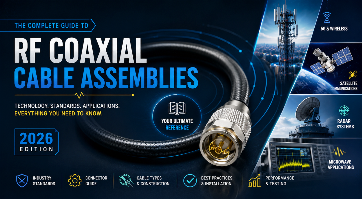
RF coaxial cable assemblies form the backbone of modern high-frequency systems. Whether you are designing a 5G base station, building a radar system, setting up test equipment, or connecting antennas in a wireless network, the right coaxial cable assembly ensures reliable signal transmission with minimal loss and interference.
This guide covers everything you need to know about RF cable assemblies from basic construction and types to connectors, real-world applications, and a practical selection process you can apply on your next project.
On This Page
What Is an RF Coaxial Cable Assembly?
A coaxial cable assembly often called a coax cable assembly or RF cable assembly consists of a length of coaxial cable terminated with connectors at one or both ends. Unlike raw cable sold by the meter, a finished assembly is a ready-to-use interconnect designed for a specific impedance, frequency range, power handling, and set of environmental conditions.
Anatomy of a Coaxial Cable
The classic coaxial structure has four concentric layers sharing a common axis:
Layer 1
Center Conductor
Solid or stranded copper (sometimes copper-clad steel) that carries the RF signal.
Layer 2
Dielectric Insulator
PTFE, polyethylene, or foam maintains precise spacing and sets characteristic impedance (typically 50 Ω for RF/microwave, 75 Ω for video and broadcast).
Layer 3
Outer Conductor / Shield
Braid, foil, or solid tubing contains the electromagnetic field and rejects external interference.
Layer 4
Outer Jacket
The protective outermost layer PVC, PE, or PTFE depending on environment, providing mechanical and environmental protection.
When these layers are correctly proportioned and the connectors are properly attached, the finished assembly can carry signals from DC into the tens of gigahertz.
Types of RF Coaxial Cable Assemblies
Not all coax cable assemblies are created equal. Performance, flexibility, and cost vary significantly by construction.
Flexible Coaxial Cable Assemblies
The most common type, using braided or foil shields. Classic RG-series cables (RG58, RG174, RG316) remain popular for short internal jumpers and lower-frequency work. Modern low-loss families such as LMR-195, LMR-240, LMR-400 and equivalents offer substantially better attenuation, better shielding effectiveness, and UV-resistant jackets suitable for outdoor use. These assemblies balance flexibility with acceptable loss up to several GHz and are widely used in cellular, Wi-Fi, and DAS installations.
Semi-Rigid and Conformable Assemblies
Use a solid or soft-annealed copper outer tube instead of braid. They deliver excellent shielding, phase stability, and low loss at microwave frequencies but cannot be repeatedly flexed after forming. Semi-rigid microwave cable assemblies are standard in aerospace, defense, and high-precision test setups. Conformable versions can be hand-formed, offering a practical middle ground.
Phase-Stable and Ultra-Low-Loss Assemblies
Use specialized dielectrics and construction techniques to minimize phase shift with temperature or bending. Essential for phased-array radar, MIMO systems, and vector network analyzer (VNA) measurements where phase accuracy is critical.
Corrugated and Hardline Cables
Appear in high-power or long-haul applications such as broadcast transmitters and cellular tower feeders. Their rigid corrugated outer conductor provides very low loss and high power handling at the expense of flexibility.
Micro-Coaxial and Miniature Assemblies
Often using 1.13 mm, 1.37 mm, or RG178-style cable, these connect modules inside compact devices, IoT sensors, and handheld radios. They typically terminate in U.FL, IPEX, MMCX, or SMA connectors.
RF Connectors Used on Coaxial Cable Assemblies
The connector is as important as the cable itself. A mismatch in impedance, frequency rating, or mechanical robustness can degrade the entire assembly.
| Connector | Frequency Rating | Typical Use |
|---|---|---|
| SMA | To 18 GHz (precision higher) | Test equipment, Wi-Fi, cellular modules, labs |
| N-Type | To 11–18 GHz | Outdoor antennas, base stations, high-power RF |
| BNC | To 4 GHz | Test benches, video (50 Ω and 75 Ω) |
| TNC | Higher than BNC | Threaded BNC alternative better vibration resistance |
| 7/16 DIN & 4.3-10 | Cellular bands | High-power, low-PIM cellular infrastructure |
| 3.5 mm / 2.92 mm / 2.4 mm / 1.85 mm | 26 GHz to 110 GHz | Precision microwave and mmWave measurement |
| MMCX / MCX / U.FL | To 6 GHz | Space-constrained designs, PCB pigtails, IoT |
Always match the connector's frequency rating, impedance, and environmental rating to the cable and application. Mixed-connector assemblies (SMA-to-N, BNC-to-SMA, etc.) are common and must be specified clearly.
Key Applications of RF Coaxial Cable Assemblies
RF coaxial cable assemblies appear across nearly every industry that uses radio frequencies.
Telecommunications and 5G
Feeder lines, jumpers between radios and antennas, DAS systems, and small-cell installations demand low-loss, low-PIM RF cable assemblies with weatherproof connectors such as N-Type or 4.3-10.
Aerospace and Defense
Radar, electronic warfare, satellite communications, and avionics require phase-stable, rugged, often MIL-SPEC microwave cable assemblies that survive extreme temperature, vibration, and altitude.
Test and Measurement
Vector network analyzers, spectrum analyzers, and signal generators rely on high-quality, phase-stable coaxial cable assemblies with precision connectors to deliver accurate measurements.
Broadcast and Video
75 Ω assemblies with F-Type or BNC connectors carry television, satellite, and CCTV signals.
Automotive and Transportation
GPS, telematics, V2X, and infotainment systems use flexible, vibration-resistant coax cable assemblies frequently with FAKRA or SMA connectors.
Industrial IoT and Medical
Compact RF cable assemblies connect sensors, wireless modules, and diagnostic equipment where space and reliability are critical.
One Cable Manufacturer, Every Assembly Type
SigmaRF builds flexible RG-series and LMR assemblies, semi-rigid microwave assemblies, mmWave assemblies up to 40 GHz, and low-PIM cellular assemblies all individually tested for VSWR, insertion loss, and continuity before shipping.
Get a Custom Assembly →Selection Guide: How to Choose the Right RF Cable Assembly
Selecting the optimal RF coaxial cable or microwave cable assembly follows a structured process. Work through these steps in order skipping any of them is where costly mistakes happen.
Step 01
Define the frequency range
The cable and connectors must perform well at the highest operating frequency. Attenuation rises with frequency, so a cable acceptable at 1 GHz may be unusable at 18 GHz or 40 GHz.
Step 02
Determine acceptable insertion loss
Calculate the loss budget. Longer runs or higher frequencies require larger-diameter, lower-loss cable (e.g., LMR-400 instead of RG58).
Step 03
Match the impedance
Almost all RF and microwave systems use 50 Ω. Video and broadcast systems use 75 Ω. Never mix the two without proper matching.
Step 04
Evaluate mechanical and environmental needs
Will the assembly be flexed repeatedly, exposed to UV, moisture, salt fog, extreme temperatures, or vibration? Choose flexible, armored, or weatherproof constructions accordingly.
Step 05
Select connectors
Match frequency rating, mating style (threaded for permanence, bayonet for convenience), power handling, and environmental sealing. Specify gender, orientation (straight or right-angle), and any special requirements such as low PIM.
Step 06
Consider phase stability and power handling
Critical for radar, phased arrays, and high-power transmitters. If either matters to your system, don't leave it as an afterthought.
Step 07
Review standards and testing
Look for assemblies tested for VSWR, insertion loss, and continuity. MIL-SPEC, RoHS, and REACH compliance may be required for certain markets.
Step 08
Balance cost and performance
Over-specifying increases expense; under-specifying risks system failure. Factory-terminated and tested assemblies generally outperform field-terminated ones for critical applications.
Two Worked Examples
Applying the eight-step process above to two very different real-world tasks:
Example A
5-metre outdoor 3.5 GHz 5G feeder
Requirements
- Low insertion loss at 3.5 GHz
- UV-resistant jacket
- Weatherproof outdoor connectors
- Low PIM for cellular use
Recommended
LMR-400-style cable with N-Type or 4.3-10 connectors.
Example B
Short internal laboratory jumper at 10 GHz
Requirements
- Excellent performance to 10 GHz
- Compact routing on a test bench
- Repeatable, phase-consistent measurements
- Indoor environment
Recommended
Flexible low-loss cable with SMA connectors, or a semi-rigid microwave assembly.
Best Practices and Common Pitfalls
Even the best-designed assembly can be compromised by installation errors.
✓ Do
- ✓ Torque threaded connectors to the manufacturer's specification.
- ✓ Respect the minimum bend radius.
- ✓ Keep assemblies as short as practical leaving service loops where needed.
- ✓ Seal outdoor connectors and add drip loops.
- ✓ Use factory-terminated, tested assemblies for critical paths.
✗ Don't
- ✗ Over-tighten it damages the center contact.
- ✗ Under-tighten it raises VSWR.
- ✗ Make sharp bends beyond the cable's minimum radius.
- ✗ Leave outdoor connectors unsealed.
- ✗ Mix 50 Ω and 75 Ω components without matching.
Ordering Checklist for Custom Assemblies
When ordering custom coax cable assemblies, provide complete specifications up front. A vague spec is the #1 cause of delayed builds and wrong deliveries.
- Cable type (e.g. RG316, LMR-240, LMR-400, semi-rigid 0.141")
- Length (with tolerance if critical)
- Connector type, gender, and orientation on each end
- Operating frequency range
- Maximum VSWR or insertion loss
- Impedance (50 Ω or 75 Ω)
- Environmental conditions (indoor, outdoor, marine, aerospace)
- Phase stability or low-PIM requirements, if any
- Compliance needs (MIL-SPEC, RoHS, REACH)
- Quantity and required delivery date
Conclusion
RF coaxial cable assemblies are far more than simple wires. They are precision transmission lines whose electrical and mechanical characteristics directly determine system performance. By understanding the differences between flexible, semi-rigid, and specialized microwave assemblies, matching the correct connectors, and following a systematic selection process, engineers and buyers can ensure reliable, low-loss signal transmission across telecommunications, aerospace, test, automotive, and industrial applications.
Whether you need a standard RG316 pigtail, a low-loss LMR-series jumper, or a phase-stable microwave cable assembly for millimeter-wave work, the principles outlined in this guide will help you choose the right coaxial cable assembly for the job. Specifying the correct RF cable assembly from the start reduces troubleshooting, improves system reliability, and ultimately delivers better RF performance.
Precision-Tested RF Cable Assemblies from SigmaRF
RG-series, LMR, semi-rigid, and precision microwave assemblies individually tested for VSWR, insertion loss, and continuity. Terminated with SMA, N-Type, BNC, TNC, 4.3-10, 3.5 mm, 2.92 mm, MMCX, U.FL and more.
Standard RF Assemblies Custom Semi-rigid Assemblies Request a Quote- Why Cheap RF Cable Assemblies Fail: Construction Shortcuts and How to Spot Them
- Solving Antenna Range Loss on an IoT Device: A Worked Diagnostic Example
- SMA Mating Cycles: How Many Connections Can an SMA Survive?
- RG58 Attenuation: Datasheet Specs vs Real-World Loss
- VNA Testing for Cable Assemblies: How VSWR and Insertion Loss Verification Works
- How a Custom Coaxial Cable Assembly Is Built, Step by Step
- Cellular Repeater and DAS Cable Selection: In-Building Coverage Guide
- Wi-Fi HaLow (802.11ah): Sub-GHz Wi-Fi and Its Antenna/Cable Needs
- RF Interconnects for Test Labs: Building a Reliable VNA Bench
- Direct-to-Cell Satellite and IoT: What It Means for Ground Hardware