Custom RF Spiral Cable Assemblies: Coiled Coax Design Guide
Published on 8/1/2026 • Updated on 8/1/2026
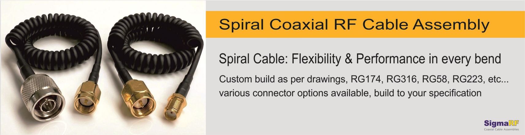
The coiled RF cable assembly (also called a retractile, curly, or spiral coax cable) solves this the same way a telephone handset cord did for a century: the cable is permanently formed into a helix that extends under light tension and springs back to its compact resting length when released. A typical coil or spiral cable extends to 3 to 5 times its retracted length, stores neatly when not stretched, and distributes flexing stress along the entire helix instead of concentrating it at one bend point, which is why coiled assemblies routinely outlast straight cables in high-motion applications.
Building one properly is a genuine engineering exercise: the cable construction, the jacket material, the spiral geometry, and the terminations all have to be chosen together. This guide covers which coaxial cables actually spiral well and why, how the coiling process works, what the coiled shape does (and doesn't do) to RF performance, the connector options at each end, and exactly how to specify a custom spiral assembly on an engineering drawing.
On This Page
- How a Coiled Coax Cable Is Made
- Which Coaxial Cables Spiral Well (and Which Don't)
- Jacket Material: Where Spiral Memory Lives
- What Coiling Does to RF Performance
- Spiral Geometry: The Parameters That Define the Assembly
- Connector Options at Both Ends
- How to Specify a Custom Spiral or Coil type Assembly
- Applications
- Frequently Asked Questions
- Bottom Line
How a Coiled Coax Cable Is Made
The retractile shape is not a spring inside the cable and not a mold. It is thermal memory set into the jacket polymer. The process:
Step 1: wind on a mandrel
The finished cable is wound helically around a precision mandrel whose diameter sets the coil's inside diameter. Winding tension and pitch are controlled; the straight tangent sections at each end are left unwound.
Step 2: heat-set
The wound assembly is held at the jacket polymer's setting temperature, typically for a period of hours, until the jacket takes a permanent helical set. Critically, the dielectric inside (PE or PTFE) has a higher softening temperature than the jacket, so the internal geometry that defines the 50 ohm impedance is not disturbed.
Step 3: cool and release
After controlled cooling, the cable comes off the mandrel holding its helix permanently. The elastic memory of the set jacket is what pulls the spiral back to its retracted length after every extension.
Step 4: terminate and test
Connectors are installed on the tangent ends with strain relief, and the finished assembly is swept on a VNA for VSWR and insertion loss like any other RF cable assembly.
Because the memory lives in the jacket, jacket material selection is the single most important decision in the whole assembly. More on that below.
Which Coaxial Cables Spiral Well (and Which Don't)
Not every coax can become a spiral. Three construction requirements are non-negotiable:
- ✓ Stranded center conductor. A coiled cable flexes on every extension cycle. A solid center conductor work-hardens and eventually fractures; a stranded conductor distributes the strain across many fine wires and survives tens of thousands of cycles.
- ✓ Braid shield, not foil-only. Aluminum foil shields crack and fragment under repeated flex, degrading shielding and creating intermittent noise. A woven copper braid flexes like fabric. High-flex designs use high-coverage braid (90 percent and up); premium designs use double braid.
- ✓ A heat-settable jacket. The jacket polymer must take a thermal set at a temperature that leaves the dielectric untouched. Polyurethane and PVC qualify. FEP and other fluoropolymer jackets (as found on RG-316 and RG-142 in stock form) resist heat-setting at practical temperatures, so those cables are typically re-jacketed before coiling.
With those rules in mind, here are the cable families used in custom coiled RF assemblies:
| Cable Base | OD | Practical Frequency | Coiling Notes |
|---|---|---|---|
| RG-174 type | 2.5 mm | To ~1 GHz (short runs) | The compact choice. Small spiral OD, light spring force. Ideal for handheld device cords and speaker mics. Higher loss, so keep total cable length modest. |
| RG-316 core, PUR re-jacket | ~2.8 mm | To ~3 GHz | PTFE dielectric core with a polyurethane jacket applied for spiral memory. Better loss and temperature performance than RG-174 in a similar size. |
| RG-58 type | 4.95 mm | To ~1 GHz | The classic radio spiral cord: stranded center, tinned braid, PVC or PUR jacket. The standard for vehicle radio and antenna coils, CB, VHF/UHF two-way. |
| RG-223 type | 5.4 mm | To ~3 GHz | Double-braid shielding (better than 90 dB) for EMI-dense environments. Stiffer spiral, larger spiral OD, stronger retraction force. |
| Custom high-flex coax | 2 to 6 mm | Application-specific | Purpose-built construction: finely-stranded silver-plated conductor, high-coverage braid, PUR jacket engineered for spiral memory. The right answer for high-cycle-life production products. |
What you will not see in coiled form: semi-rigid cable (the solid copper tube takes one bend, permanently), LMR-style cables with bonded foil-plus-braid shields (the foil layer fails under cyclic flex), and air-dielectric cables (the coiling would crush the spacing). If your loss budget genuinely demands those constructions, the design answer is usually a short coiled section of flexible cable at the moving joint, spliced into a low-loss straight run for the distance.
Jacket Material: Where Spiral Memory Lives
The jacket does the mechanical work in a coiled assembly, so it gets chosen with more care than on a straight cable:
Polyurethane (PUR): the retractile standard
Outstanding elastic memory (the spiral snaps back crisply for years), excellent abrasion resistance, good resistance to oils and fuels, flexible at low temperatures. This is why nearly every professional-grade coiled cord, from military radio cords to industrial pendants, wears polyurethane. The premium choice and worth it for any assembly that will cycle daily.
PVC: the economical option
Heat-sets readily and costs less. The trade-offs: spiral memory softens over time and with temperature (a PVC spiral left extended in a hot vehicle can take a partial set in the stretched position), and low-temperature flexibility is poorer. Appropriate for indoor, moderate-duty, and cost-driven applications.
Jacket color, by the way, is a free variable: black is standard, but coiled assemblies are routinely produced in colors for equipment identification or brand matching.
What Coiling Does to RF Performance
A question every engineer asks the first time: doesn't winding a cable into a spiral turn it into an inductor? For the signal inside the coax, no. The fields of the signal are entirely confined between the center conductor and the shield; the cable's impedance is set by that internal geometry, which the helix does not change. A properly made 50 ohm coiled assembly measures 50 ohms, extended or retracted.
Three real effects do exist, and honest specification accounts for them:
1. Loss follows cable length, not reach
A spiral coaxial cable that reaches 1.5 m when extended may contain 4 to 6 m of actual cable. Insertion loss is computed on the actual cable length. At VHF/UHF with RG-58-class cable this is a fraction of a dB and irrelevant; at 2.4 GHz with small coax it becomes a real line item. Always run the loss budget on the wound length.
2. The exterior of the shield becomes a common-mode choke
While the internal signal is unaffected, current flowing on the outside surface of the shield does see the helix as an inductance. In many installations this is a quiet bonus: the spiral suppresses common-mode currents and RF pickup on the cable exterior, the same principle used deliberately in coax choke baluns. It is rarely a problem and occasionally a feature.
3. Flex cycling is the life limit
The failure mode of a coiled assembly is mechanical fatigue, concentrated where the tangent meets the connector and where the tangent meets the first spiral turn. Proper stranding, braid construction, strain relief boots, and adequate tangent length are what push cycle life from thousands into tens of thousands of extensions. This is where build quality separates suppliers.
Spiral Geometry: The Parameters That Define the Assembly
A coiled assembly is specified by a handful of dimensions. Learn these terms and you can read or write any spiral cord drawing:
| Parameter | What It Means |
|---|---|
| Retracted length | Length of the coiled section at rest, coils touching. This is the storage length. |
| Working (extended) length | The reach at which the assembly operates comfortably day to day. Typically 3 to 4 times the retracted length for long service life. |
| Maximum extension | The absolute stretch limit, around 5 times retracted length, beyond which the jacket's set is damaged and the spiral no longer fully recovers. Spec the working length with margin below this. |
| spiral OD / ID | Outside and inside diameter of the helix. Set by the mandrel and the cable OD. Larger spiral OD gives gentler bending of the cable (longer life) but a bulkier spiral. |
| Tangents (legs) | The straight coaxial cable sections at each end, between the last coil turn and the connector. Independently specified per end; they route the cable from the spiral / coil to the equipment. |
| Tangent orientation | Axial (the tangent exits along the coil's axis, in line) or radial/perpendicular (the tangent exits sideways from the coil). Chosen to suit the installation geometry. |
| Number of turns and pitch | Usually derived by the manufacturer from the retracted and extended lengths rather than specified directly. |
| Retraction force / spring rate | How firmly the spiral or coil pulls back. A shoulder-mic cord should extend with two fingers; an industrial pendant spiral can be much stiffer. Influenced by cable OD, jacket, coil OD, and heat-set schedule. |
On length availability: because every spiral is wound and heat-set as a distinct operation, lengths are genuinely custom. Retracted lengths from roughly 100 mm up to 2 m and working lengths from under half a meter to 10 m and beyond are all manufacturable, with tangents from a few centimeters to several meters per end. The controlling document is your drawing, not a catalog list.
Custom Coiled RF Assemblies, Built to Your Drawing
SigmaRF builds coiled coaxial cable assemblies to specification: your retracted and working lengths, tangent lengths and orientation, cable construction, jacket material and color, and connector pair. Prototypes through production, every assembly VNA-tested for VSWR and insertion loss before shipment.
Request a Custom Spiral Coaxial Assembly →Connector Options at Both Ends
Any connector that fits the cable can terminate a coiled assembly, and mixed pairs (one type at each end) are the norm rather than the exception, since the two ends usually mate to different equipment. Common choices by role:
| Connector | Coupling | Typical Role on Coiled Assemblies |
|---|---|---|
| BNC | Bayonet | Test equipment, instrumentation, lab probe cords where quick connect matters |
| TNC | Threaded | Vehicle and field radio, telemetry, anywhere vibration would loosen a bayonet |
| SMA / RP-SMA | Threaded | Compact radios, modules, GPS receivers, Wi-Fi equipment |
| N-Type | Threaded | Base station and antenna ends, outdoor-rated interfaces |
| UHF (PL-259) / Mini-UHF | Threaded | CB, amateur, and land-mobile radio equipment |
| FME | Threaded, small | Vehicle installations: small enough to feed through grommets and panels, adapted to the final interface at each end |
| SMB / MCX / MMCX | Snap-on | Compact equipment interiors, GPS and telematics modules |
All are available in male and female, and most in right-angle as well as straight bodies. Right-angle connectors earn their keep on coiled assemblies: at a belt-worn radio or a dash-mounted transceiver, a right-angle exit keeps the tangent flat against the equipment instead of sticking out where it gets levered.
How to Specify a Custom Spiral Assembly
A complete specification, whether as an engineering drawing or a written requirement, covers these items. Send this list filled in and any competent manufacturer can quote without a single follow-up question:
- ✓ Electrical: impedance (50 or 75 ohm), operating frequency range, maximum insertion loss at the working extension, minimum return loss or maximum VSWR
- ✓ Cable: preferred base cable (RG-174, RG-58, RG-316 core, RG-223, or "manufacturer's recommendation to meet spec"), shield requirement if EMI-critical
- ✓Spiral geometry: retracted length, working extended length, coil OD limit if space-constrained, retraction feel if it matters (light, medium, firm)
- ✓ Tangents: length at each end, axial or radial exit at each end
- ✓ Connectors: type, gender, and body style (straight or right-angle) at each end, plating preference if any
- ✓ Environment: temperature range, outdoor or indoor, oil/fuel exposure, expected flex cycles per day or over life
- ✓ Cosmetic and identification: jacket color, labeling, heat-shrink marking
- ✓ Quantities: prototype quantity now, production forecast, since mandrel tooling amortizes across the run
If you have only a sketch and a use case, that works too. Describing "handheld radio on the belt, antenna on the shoulder, needs to reach 1.2 m without tugging" gives a manufacturer enough to propose the geometry, and the drawing gets formalized from the first article.
Applications
Two-way radio speaker mics Military man-pack radio antenna cords Vehicle antenna to transceiver runs Test probes and bench cords Broadcast and intercom headsets Portable medical devices Robotics and moving machinery Handheld GPS and telemetry
The common denominator: two pieces of equipment whose separation changes during use, in the sub-GHz to low-GHz range where flexible coax loss over a few meters of wound cable is affordable, and where a dangling straight cable would be a snag hazard, a strain source, or both.
Frequently Asked Questions
Does coiling a coax cable change its impedance?
No. The impedance of a coaxial cable is set by the internal geometry between the center conductor and shield, and the signal's fields are entirely confined inside that geometry. The heat-set process shapes only the jacket; the dielectric is unaffected. A 50 ohm coiled assembly measures 50 ohms whether retracted or extended. The one external effect is that the coiled shield exterior acts as a common-mode choke, which usually helps rather than hurts.
How far can a coiled cable stretch?
Typical coiled cables extend to 3 to 5 times their retracted length. For long service life, specify the everyday working length at 3 to 4 times retracted, keeping the 5-times figure as an occasional maximum. Repeatedly stretching a spiral to or past its maximum damages the jacket's thermal set, and the spiral stops returning fully to its retracted length.
What cable is used in coiled RF assemblies?
Flexible coax with a stranded center conductor, a braided (not foil) shield, and a heat-settable jacket. Common bases are RG-174 and RG-316-core constructions for compact cords, RG-58 for classic radio and vehicle cords, RG-223 where double-braid shielding is needed, and purpose-built high-flex coax with polyurethane jackets for production products. Semi-rigid and foil-shielded low-loss cables cannot be coiled.
Why is polyurethane the preferred jacket for coiled cords?
Polyurethane combines excellent elastic memory (the property that makes the spiral retract crisply for years), high abrasion resistance, oil and fuel resistance, and flexibility at low temperatures. PVC also heat-sets and costs less, but its spiral memory relaxes with time and heat, which is why professional and military coiled cords are almost universally polyurethane-jacketed.
How do I calculate the loss of a coiled cable assembly?
Use the actual wound cable length, not the reach. A spiral with 1.5 m of working reach may contain 4 to 6 m of cable, and insertion loss follows the cable. Multiply the cable's dB-per-meter figure at your frequency by the total cable length, then add roughly 0.1 to 0.2 dB per connector. Your manufacturer can state the exact wound length from the spiral design.
What lengths are available for custom coiled cable assemblies?
Effectively any length within the physics: retracted lengths from about 100 mm to 2 m, working lengths from under half a meter to 10 m or more, and tangent (straight leg) lengths from a few centimeters to several meters at each end, each independently specified. Because every spiral is wound and heat-set to order, the controlling document is your engineering drawing rather than a catalog size list.
What connectors can be fitted to a coiled coax assembly?
Any connector compatible with the cable diameter: BNC, TNC, SMA, RP-SMA, N-Type, UHF (PL-259), Mini-UHF, FME, SMB, MCX, and MMCX, in male or female and straight or right-angle bodies, with different types at each end as the equipment requires. Right-angle bodies and strain relief boots are particularly valuable on coiled assemblies because the tangent-to-connector junction carries the retraction force on every cycle.
Bottom Line
A coiled RF cable assembly is a mechanical spring and a transmission line sharing one body, and it only works well when both roles are engineered together. The cable must be built to flex (stranded conductor, braided shield), the jacket must be chosen for memory (polyurethane for professional duty), the coil geometry must match the real motion of the installation (working length at 3 to 4 times retracted, tangents and exits that suit the equipment), and the terminations must be strain-relieved to survive the cycle count.
Specify those elements deliberately (the checklist above covers all of them) and the result is an interconnect that reaches when pulled, disappears when released, keeps 50 ohms throughout, and outlives the equipment it connects. Leave them to chance and you get the familiar failure: a stretched-out cord that no longer retracts, crackling at one connector after a year of service.
Custom Coiled RF Cable Assemblies from SigmaRF
Retractile coax assemblies built to your drawing: RG-174, RG-58, RG-316-core, RG-223, and custom high-flex constructions, polyurethane or PVC jackets in your color, any connector pair from BNC and TNC to SMA, N-Type, UHF, and FME, with strain relief engineered for the cycle life your application demands. Every assembly VNA-tested before shipment, prototype through production.
Custom Spiral Cable Assemblies Standard Assemblies Talk to an Engineer- Why Cheap RF Cable Assemblies Fail: Construction Shortcuts and How to Spot Them
- Solving Antenna Range Loss on an IoT Device: A Worked Diagnostic Example
- SMA Mating Cycles: How Many Connections Can an SMA Survive?
- RG58 Attenuation: Datasheet Specs vs Real-World Loss
- VNA Testing for Cable Assemblies: How VSWR and Insertion Loss Verification Works
- How a Custom Coaxial Cable Assembly Is Built, Step by Step
- Cellular Repeater and DAS Cable Selection: In-Building Coverage Guide
- Wi-Fi HaLow (802.11ah): Sub-GHz Wi-Fi and Its Antenna/Cable Needs
- RF Interconnects for Test Labs: Building a Reliable VNA Bench
- Direct-to-Cell Satellite and IoT: What It Means for Ground Hardware