Electrical vs Mechanical Antenna Tilt: Engineer's Guide + Math
Published on 7/28/2026 • Updated on 8/1/2026
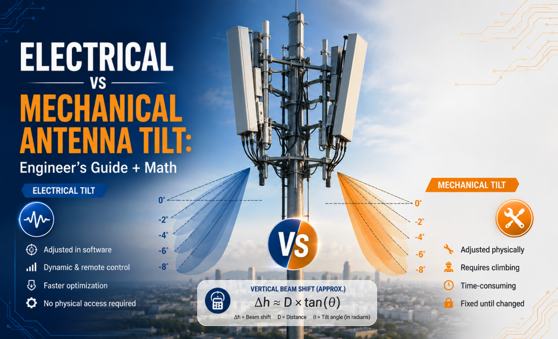
There are two ways to change where an antenna's main beam points: rotate the whole antenna physically (mechanical tilt), or shift the phase relationship between its internal radiating elements (electrical tilt). They sound similar. They are not. Understanding the difference is one of the fundamental competencies of RF network planning, and getting the choice wrong is one of the most common causes of poor cell-edge performance in real networks.
This guide covers how each type of tilt actually works, the math for choosing a tilt angle, when to use one or the other (or both), and the RF infrastructure that has to be right for either to work in practice.
On This Page
- What Antenna Tilt Really Does
- Why We Tilt Antennas
- Mechanical Tilt: How It Works
- Electrical Tilt: How It Works
- Remote Electrical Tilt (RET) and AISG
- Electrical vs Mechanical: Side by Side
- Calculating the Right Tilt Angle
- Tilt Angle Reference Table
- Why Beamwidth Matters More Than Tilt Alone
- Frequency-Specific Tilt Considerations
- Combining Mechanical and Electrical Tilt
- Application-Specific Tilt Guidance
- The RF Infrastructure Behind the Antenna
- Common Tilt Mistakes
- Frequently Asked Questions
- Bottom Line
What Antenna Tilt Really Does
A sector antenna does not radiate uniformly in all directions. It has a beam pattern with a defined main lobe, a set of side lobes, and specific vertical and horizontal beamwidths. Tilt controls where the peak of that main lobe points.
At zero degrees of tilt, a horizontally polarized sector antenna points its main beam at the horizon. Most of the RF energy travels parallel to the ground. Users directly below the tower are in the antenna's lower side lobes, where gain is 15 to 20 dB below the main beam. Far-away users get plenty of signal but so does everything else in the beam's path, including neighboring cells.
Tilting the antenna downward moves the peak of the main beam closer to the tower. Local coverage improves. Distant coverage shrinks. Inter-cell interference drops. These trade-offs are the whole game in cellular network planning.
Why We Tilt Antennas
Four things happen when you apply the correct downtilt to a sector antenna:
Better local coverage
Users near the tower are now in the main beam instead of a side lobe. RSRP typically improves by 5 to 15 dB in the near-cell area.
Lower interference to neighbors
Beam energy that used to spill into adjacent cells now hits the ground before it gets there. Neighboring sectors see less noise, improving their SINR.
Higher network capacity
Cleaner cell boundaries mean better frequency reuse, higher modulation orders, and more bits per Hz across the network.
Cleaner handovers
Sharper cell edges reduce the "ping-pong" handover behavior that hurts VoLTE, video calling, and mobility scenarios.
Mechanical Tilt: How It Works
Mechanical tilt is exactly what it sounds like. The whole antenna is physically rotated on its mount so the top leans back and the front face points slightly downward. The antenna itself does not change. Only its orientation in space changes.
On a typical macro-cell antenna, the mounting bracket has adjustable pins or clamps that allow 0 to 10 degrees of mechanical tilt. A tower rigger loosens the bracket, sets the angle with an inclinometer, and locks it down.
Advantages of mechanical tilt
- Simplest possible mechanism, cheap and reliable
- Works on any antenna, no special electronics required
- Set-and-forget: once installed, does not drift
- Can achieve very large tilt angles (up to 10 degrees or more)
The problem with mechanical tilt
When you tilt the whole antenna downward, you also tilt the horizontal beamwidth. What was a nice symmetric 65-degree sector at the horizon becomes a distorted, asymmetric pattern that gets narrower on one side and wider on the other. At 8 degrees of mechanical tilt, the effective horizontal beamwidth can shift by several degrees, and the sector's coverage boundary is no longer where the RF plan says it should be.
This is why mechanical tilt above 4 to 6 degrees is generally avoided in modern LTE and 5G networks: the pattern distortion becomes larger than the tilt correction is worth.
Electrical Tilt: How It Works
Electrical tilt does the same job (moves the main beam downward) but does it entirely through phase manipulation inside the antenna. Nothing physically rotates. The antenna stays vertical on the mast, and yet its main beam points several degrees below the horizon.
Here is how the physics works. A modern base station antenna contains a vertical array of individual radiating elements, typically 8 to 12 of them stacked one above the other. When the same signal drives all of them in phase, the array's radiation pattern peaks perpendicular to the array (broadside, at the horizon). By feeding each element with a progressive phase delay (element 1 at 0 degrees, element 2 at −10 degrees, element 3 at −20 degrees, and so on), the constructive interference between the elements shifts downward from broadside. The main beam tilts down by a specific angle determined by the phase progression and the element spacing.
Crucially, this happens without changing the horizontal pattern. The elements are still radiating with the same horizontal symmetry. Only the vertical direction of the peak has moved. This is why electrical tilt preserves the sector's horizontal beamwidth (typically 65 degrees for a three-sector site) across the full tilt range.
Advantages of electrical tilt
- Horizontal beamwidth stays symmetric across the whole tilt range
- Antenna stays visually vertical; no unusual tower shadow
- Fine adjustment steps (0.1 to 0.5 degrees on RET-equipped antennas)
- Remote adjustment possible with RET (no tower climb)
- Preferred method for modern LTE and 5G deployments
Limitations of electrical tilt
- More complex, more expensive antenna
- Limited maximum tilt (usually 0 to 12 degrees, sometimes 14)
- Motorized RET adds a mechanical part that can fail
- Requires an AISG-compatible controller and RET control cable
Remote Electrical Tilt (RET) and AISG
Modern base station antennas are almost always RET-equipped. A small motor inside the antenna drives a phase-shifting mechanism, and a serial data connection lets the network operations center command a specific tilt angle from anywhere in the world. Tower climbs to adjust tilt are essentially extinct on managed macro networks.
The industry protocol behind this is AISG (Antenna Interface Standards Group), currently at version 2.0 and 3.0. AISG defines the physical connector (an 8-pin circular connector), the electrical interface (RS-485 over DC power), and the command set that lets a controller query and set tilt, read back position, get diagnostic information, and coordinate multiple RET modules on the same antenna or tower.
A typical RET system includes:
- An AISG controller at the base of the tower or inside the RRU cabinet
- A bias-T that multiplexes the DC power and RS-485 data onto the RF feeder, or a dedicated RET control cable
- The RET actuator inside the antenna, with an 8-pin AISG connector
- An OMC (operations and maintenance center) interface that manages tilt commands across the fleet
RET tilt adjustments happen in fine steps (typically 0.1 to 0.5 degrees) and complete in a few seconds. Modern network optimization tools automate tilt adjustments across large fleets, sometimes in response to load, time-of-day traffic patterns, or events.
Electrical vs Mechanical: Side by Side
| Feature | Mechanical Tilt | Electrical Tilt |
|---|---|---|
| What moves | Whole antenna physically | Internal phase, no physical rotation |
| Horizontal pattern | Distorts at higher angles | Preserved across tilt range |
| Adjustment range | 0 to 10° typical | 0 to 12° (some 14°) |
| Adjustment resolution | Whole degrees | 0.1 to 0.5° steps |
| Remote control | No, requires tower climb | Yes with RET/AISG |
| Antenna cost | Lower | Higher (RET adds cost) |
| Operational cost | Higher (tower climbs) | Lower (remote adjustment) |
| Reliability | No moving parts once set | Motor and gearbox can fail |
| Best use | Initial alignment, small sites, broadcast | LTE / 5G macro, dense urban, RET networks |
Low-PIM Jumpers for the RRU-to-Antenna Path
The antenna tilt is only half the story. The other half is the jumper between the RRU and the antenna port. SigmaRF builds 4.3-10 and 7/16 DIN low-PIM cable assemblies, weatherproof and torque-verified, individually swept for VSWR before shipment. When your RET is on target, your jumper should not be the reason the sector underperforms.
Get a Custom Assembly →Calculating the Right Tilt Angle
Tilt angle is not a guess. It is a trigonometry problem based on antenna height and where you want the main beam to hit the ground. The basic geometry:
Tilt angle formula
where:
antenna_height = height above the target (meters)
target_distance = horizontal distance to where you
want the main beam to hit ground level (meters)
There is a subtlety. This formula gives you the angle at which the main beam peak hits the ground at target_distance. In practice, you want the coverage to extend somewhat past that point, so most planners aim the main beam at about two-thirds of the intended cell edge. The remaining coverage comes from the lower half of the beam's vertical pattern.
Worked example
A cellular sector on a 30 m rooftop, targeting a 500 m cell radius, aimed at two-thirds of the cell edge (about 333 m).
aim_distance: 333 m (2/3 of 500 m)
tilt = arctan(30 / 333) = arctan(0.090)
tilt = 5.1 degrees
Split this across mechanical and electrical: a common approach is 2 degrees mechanical (for initial alignment during installation) plus 3 degrees electrical (fine-tuned via RET after coverage measurement). This keeps mechanical tilt low enough to preserve horizontal pattern integrity while giving the network optimization team room to adjust the electrical tilt over time.
Tilt Angle Reference Table
Total downtilt needed to aim the main beam at two-thirds of the cell edge, for common antenna heights and cell radii.
| Antenna Height | 300 m Radius | 500 m Radius | 1000 m Radius | 2000 m Radius |
|---|---|---|---|---|
| 15 m | 4.3° | 2.6° | 1.3° | 0.6° |
| 25 m | 7.1° | 4.3° | 2.1° | 1.1° |
| 30 m | 8.5° | 5.1° | 2.6° | 1.3° |
| 40 m | 11.3° | 6.8° | 3.4° | 1.7° |
| 50 m | 14.0° | 8.5° | 4.3° | 2.1° |
| 60 m | 16.7° | 10.2° | 5.1° | 2.6° |
Values above 10 degrees start to exceed what a single antenna can deliver purely electrically. In tall, small-radius scenarios (a 60 m tower serving a 300 m urban cell), you might need combined mechanical + electrical tilt, a downward-facing microcell, or an antenna with a wider vertical beamwidth. Values under 2 degrees suggest you have too much range and are probably contributing to neighboring cell interference.
Why Beamwidth Matters More Than Tilt Alone
The tilt number by itself does not tell you where the beam actually reaches full or half power. You need to know the antenna's vertical half-power beamwidth (HPBW). A typical 65-degree horizontal sector antenna has a vertical HPBW between 5 and 12 degrees depending on the antenna's electrical length.
Two implications matter for tilt planning:
- An antenna with a 6-degree vertical HPBW tilted 3 degrees down still has its upper half-power point above the horizon, meaning far-field energy is still spilling out. To fully contain the beam below the horizon, you need tilt greater than half the HPBW plus some margin.
- Higher-gain antennas (18 dBi and above) have narrower vertical beamwidths (typically 4 to 6 degrees). They require less tilt to fully contain the beam but are also less forgiving of tilt errors. A 1-degree tilt error on a 5-degree HPBW antenna is a bigger deal than on a 10-degree HPBW antenna.
This is why RF planning tools look at the full radiation pattern, not just the tilt number. What matters is where the beam is at −3 dB, at −10 dB, and at the null. Tilt is the mechanism; the pattern is the outcome.
Frequency-Specific Tilt Considerations
Different bands behave differently at the same tilt.
| Band | Typical Vertical HPBW | Tilt Notes |
|---|---|---|
| 700-900 MHz | 6 to 12° | Coverage band, lower tilt (0-4°) preserves reach |
| 1.8-2.1 GHz | 4 to 8° | Capacity band, moderate tilt (2-6°) common |
| 2.6 GHz | 4 to 6° | Capacity band, tighter tilt (4-8°) for reuse |
| 3.5 GHz (n78) | 4 to 6° | Massive MIMO changes the picture, beamforming |
| 26/28/39 GHz mmWave | 2 to 4° | Highly directional, tilt via beamforming controller |
Multi-band antennas often have independent electrical tilt per band. You might run 700 MHz at 2 degrees for coverage, 1.8 GHz at 4 degrees, and 3.5 GHz at 6 degrees for capacity, all on the same physical antenna. Modern RET systems support per-band control.
Combining Mechanical and Electrical Tilt
The best cellular deployments use both. The common approach:
Layer 1
Mechanical tilt: coarse initial alignment
Set at installation time to about half the intended total tilt (typically 2 to 4 degrees). This aligns the antenna with the general cell coverage and reduces the electrical tilt range required.
Layer 2
Electrical tilt: precision remote optimization
Set via RET after coverage measurement, in fine 0.1 to 0.5 degree steps. Adjusted over the life of the site as traffic patterns change, new sites are added nearby, or optimization software recommends changes.
This split gives you the coverage aim from mechanical tilt without pushing it far enough to distort the horizontal pattern, while keeping most of the tunable range in electrical tilt where remote adjustment is possible.
Application-Specific Tilt Guidance
| Scenario | Typical Total Tilt | Reasoning |
|---|---|---|
| Dense urban macro | 6 to 10° | Small cells, need aggressive interference control |
| Suburban macro | 3 to 6° | Balance of range and reuse |
| Rural macro | 1 to 3° | Coverage is the priority, interference low |
| Highway coverage | 2 to 4° | Direct beam along the roadway |
| Stadium | 6 to 10° | Contain RF within venue, avoid overspill |
| Airport terminal | 4 to 8° | Even coverage inside, no interference to ATC |
| Rooftop micro | 4 to 8° | Short range, tight cell definition |
| Outdoor Wi-Fi sector | 4 to 10° | Aim at users, avoid neighboring APs |
The RF Infrastructure Behind the Antenna
Antenna tilt controls where the beam points. But the beam only carries the signal that the RF interconnect between the RRU and the antenna port delivers to it. Every dB lost in the jumper is a dB the antenna cannot radiate. Every PIM product created in a poor connector interface shows up as receiver noise, and no amount of tilt correction fixes it.
The RRU-to-antenna path typically involves:
- A short jumper from the RRU output to the tower feeder, usually 1 to 3 meters of low-loss cable with 4.3-10 or 7/16 DIN connectors
- The main feeder up the tower (increasingly replaced by fiber + RRU-at-antenna architecture)
- A short top jumper from the tower termination to the antenna port, again typically 4.3-10 or 7/16 DIN, and expected to be low-PIM
- The RET control cable, AISG 8-pin, running from the AISG controller up to the antenna
What matters for these jumpers:
- ✓ Low PIM: better than −155 dBc typical, better than −160 dBc for high-density urban 5G
- ✓ Low loss: spec'd across the operating band, individually swept per assembly
- ✓ Low VSWR: 1.15:1 or better across the band
- ✓ Weatherproof interfaces: IP67 or better, with sealing boots or self-amalgamating tape
- ✓ Torque-verified: torqued to connector spec at installation, not hand-tight
- ✓ Mechanical robustness: can survive tower vibration, thermal cycling, and UV exposure for the life of the site
Get any of these wrong and the antenna's carefully tuned tilt is delivering a compromised signal. This is why the jumpers are as important as the antenna they connect to.
Common Tilt Mistakes
- ✗ Using excessive mechanical tilt (above 6 degrees) and getting distorted horizontal patterns.
- ✗ Ignoring vertical beamwidth when choosing a tilt angle. Tilt matters only relative to the pattern width.
- ✗ Setting the same tilt across all bands on a multi-band antenna instead of using per-band electrical tilt.
- ✗ Assuming more tilt is always better. Overtilt creates coverage holes at the cell edge and dropped calls.
- ✗ Ignoring terrain: a tilt setting that works on flat ground creates coverage problems on hills.
- ✗ Setting electrical tilt via RET without verifying the actuator reached the commanded position.
- ✗ Blaming the antenna or RET when the real problem is a poor jumper or damaged connector.
- ✗ Forgetting to update tilt records after remote adjustments, making future optimization harder.
- ✗ Not doing drive tests after tilt changes. Simulated coverage is not real coverage.
Frequently Asked Questions
What is the difference between electrical tilt and mechanical tilt?
Mechanical tilt physically rotates the entire antenna on its mount, changing where its main beam points but also distorting the horizontal radiation pattern. Electrical tilt achieves the same beam redirection by adjusting the phase relationships between the antenna's internal radiating elements, preserving the horizontal pattern while pointing the main beam downward. Electrical tilt is preferred for modern LTE and 5G networks because it maintains coverage symmetry and supports remote adjustment.
What is Remote Electrical Tilt (RET)?
RET is a motorized electrical tilt system inside a base station antenna, controlled remotely over the AISG protocol. It lets network operators change tilt from the operations center in fine 0.1 to 0.5 degree steps without climbing the tower. Modern cellular networks use RET as their primary tool for coverage and interference optimization.
What is AISG in antenna systems?
AISG (Antenna Interface Standards Group) is the industry standard for communication between base station antennas and their controllers. AISG defines the 8-pin control connector, the RS-485 serial protocol, and the command set for setting tilt, reading position, and managing RET actuators. Current versions are AISG 2.0 and 3.0.
How do I calculate antenna tilt angle?
Tilt = arctan(antenna_height / target_distance), where target_distance is the horizontal distance from the tower to where you want the main beam to hit the ground. Common practice is to aim at two-thirds of the intended cell edge distance, so coverage extends past the aim point through the beam's lower half. For a 30 m antenna targeting a 500 m cell radius, tilt = arctan(30 / 333) = about 5.1 degrees.
What is a typical downtilt for cellular antennas?
Dense urban macros typically run 6 to 10 degrees total downtilt. Suburban is 3 to 6 degrees. Rural is 1 to 3 degrees. Stadium and event venues run 6 to 10 degrees to contain RF within the space. Most modern deployments split this between about 2 to 4 degrees mechanical and the remainder electrical, with the electrical portion adjustable via RET.
Can I use electrical and mechanical tilt at the same time?
Yes, and modern cellular deployments usually do. A small mechanical tilt (2 to 4 degrees) provides coarse initial alignment during installation. Electrical tilt via RET provides the fine adjustments and remote optimization. This split maximizes tunability without pushing mechanical tilt to the point of horizontal pattern distortion.
Does more antenna tilt always improve coverage?
No. Increasing tilt improves coverage close to the tower but shrinks the cell radius. Overtilt causes weak signals at the cell edge, more dropped calls, and unnecessary handovers. The correct tilt is a balance between covering your intended cell area and containing the beam so it does not interfere with neighboring cells.
What is the maximum tilt angle for a cellular antenna?
Typical maximum mechanical tilt is 10 degrees, though pattern distortion becomes noticeable above 6 degrees. Typical maximum electrical tilt is 12 degrees (some antennas support 14). Combined mechanical plus electrical can reach 15 to 20 degrees but is rarely needed except for tall towers with small cells or urban microcell scenarios.
Do 5G massive MIMO antennas still use tilt?
Massive MIMO antennas use beamforming rather than a fixed sector beam, so "tilt" becomes a per-user or per-beam concept controlled by the RRU's digital beamforming rather than a mechanical actuator. However, the antenna array still has a physical broadside direction, and some form of mechanical or electrical alignment still applies. Multi-band antennas often combine a fixed sector for lower bands with an active MIMO array for higher bands, each with its own tilt logic.
Bottom Line
Antenna tilt is not a set-and-forget parameter. It is the primary lever that RF planning uses to balance coverage against interference, and getting it right is the difference between a network that delivers rated performance and one that limps along wondering why cell-edge users cannot hold a call.
Mechanical tilt is the simple, robust method: rotate the whole antenna. Fine for coarse alignment and small sites, distorts the horizontal pattern above 6 degrees. Electrical tilt uses phase shifting inside the antenna to move the beam without rotating the antenna, preserving the pattern and supporting fine adjustment. Combined with RET and the AISG protocol, electrical tilt is what makes modern cellular network optimization possible.
Calculate the target angle from tower height and coverage distance, split it between mechanical for initial alignment and electrical for fine optimization, verify with drive tests, and revisit the setting as the network evolves. And do not forget that the tilt only matters if the RF signal reaching the antenna is clean. Every dB lost in a poor jumper is a dB the perfectly aimed antenna cannot radiate.
RF Cable Assemblies for Cellular Infrastructure
Low-PIM 4.3-10 and 7/16 DIN jumper assemblies for the RRU-to-antenna path. Individually swept for VSWR and insertion loss, weatherproof, torque-verified, built for 4G and 5G cellular deployments where every dB and every PIM product matters. SigmaRF also builds standard SMA, N-Type, and TNC assemblies for control cables, antenna testing, and adjacent RF infrastructure.
Standard Assemblies Custom Assemblies Talk to an Engineer- Why Cheap RF Cable Assemblies Fail: Construction Shortcuts and How to Spot Them
- Solving Antenna Range Loss on an IoT Device: A Worked Diagnostic Example
- SMA Mating Cycles: How Many Connections Can an SMA Survive?
- RG58 Attenuation: Datasheet Specs vs Real-World Loss
- VNA Testing for Cable Assemblies: How VSWR and Insertion Loss Verification Works
- How a Custom Coaxial Cable Assembly Is Built, Step by Step
- Cellular Repeater and DAS Cable Selection: In-Building Coverage Guide
- Wi-Fi HaLow (802.11ah): Sub-GHz Wi-Fi and Its Antenna/Cable Needs
- RF Interconnects for Test Labs: Building a Reliable VNA Bench
- Direct-to-Cell Satellite and IoT: What It Means for Ground Hardware