How to Measure RF Cable Loss Accurately: VNA and Field Guide
Published on 7/28/2026 • Updated on 8/1/2026
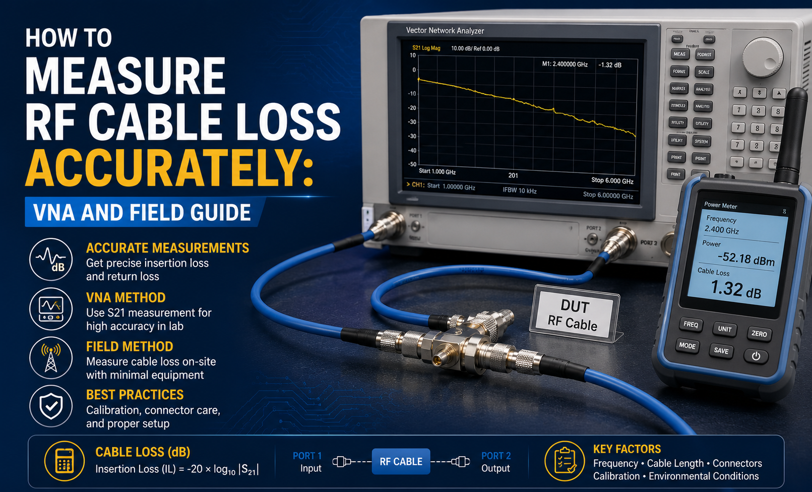
Every RF cable loses some signal. The number on the datasheet is the manufacturer's promise. The number on your bench is the truth. When those two disagree, one of them is wrong, and finding out which is the whole point of learning to measure cable loss properly.
Most engineers think of cable loss measurement as "put it on the VNA and read S21." That works, until it does not. A poorly calibrated VNA can be off by half a dB. A worn test cable can add another half. A dirty connector can add a third. Measurement error stacks, and if you do not know how much of it you have, you do not know whether your cable is out of spec or your setup is lying to you.
This guide walks through how to actually measure RF cable loss so the answer is trustworthy: which instruments make sense at which accuracy, how to calibrate a VNA correctly, what test setup mistakes will bite you, and how to read results in a way that survives peer review.
On This Page
- What Cable Loss Actually Is
- Why Accurate Measurement Matters
- Reading Loss Numbers: What They Cost You
- The Four Measurement Methods
- Method 1: RF Power Meter
- Method 2: Spectrum Analyzer + Tracking Generator
- Method 3: Vector Network Analyzer (VNA)
- Method 4: Time-Domain Reflectometry (TDR)
- Method Comparison at a Glance
- VNA Calibration: What You Actually Need to Know
- Six-Step VNA Measurement Procedure
- Worked Example: Measuring an LMR-400 Assembly
- What Affects Measurement Accuracy
- Test Cable Requirements
- Common Measurement Mistakes
- Frequently Asked Questions
- Bottom Line
What Cable Loss Actually Is
RF cable loss, also called insertion loss or attenuation, is the reduction in signal power between the input and output of a coaxial cable. It is expressed in decibels (dB) and is always positive when quoted as a loss ("3 dB of loss") or negative when quoted as S21 magnitude on a VNA trace ("−3 dB").
Loss comes from four mechanisms working together: conductor resistance (the skin effect), dielectric absorption, small imperfections in the shield, and the impedance transitions at each connector. All four contribute simultaneously and vary with frequency. When you measure S21 on a VNA, you are seeing the sum of all of them.
Why Accurate Measurement Matters
Every workflow that touches RF cable eventually needs an honest loss number.
- Manufacturing QC: is every assembly on the production line meeting the datasheet spec?
- Incoming inspection: did the assembly ship with the performance it claimed?
- System budgeting: what actual link loss should you plan for at your operating frequency?
- Field troubleshooting: has an installed cable degraded, and by how much?
- Compliance testing: does the installed system meet the regulator's or customer's acceptance criteria?
- Root-cause investigation: is the cable the reason the link is failing, or something else?
None of these are answered by a datasheet quote. All of them are answered by a proper measurement.
Reading Loss Numbers: What They Cost You
Before you can tell whether a measured number is acceptable, you need a working sense of what dB values actually cost. Because dB is logarithmic, a small numerical difference is often a large real difference.
| Insertion Loss | Power That Gets Through | Power Lost as Heat | In Practice |
|---|---|---|---|
| 0.1 dB | 97.7% | 2.3% | Precision test cable |
| 0.5 dB | 89.1% | 10.9% | Short lab jumper |
| 1.0 dB | 79.4% | 20.6% | Reasonable field assembly |
| 3.0 dB | 50.1% | 49.9% | Half your power gone |
| 6.0 dB | 25.1% | 74.9% | Three-quarters lost |
| 10 dB | 10.0% | 90.0% | Only a tenth reaches the far end |
If your VNA reads 3.2 dB where the datasheet says 2.4 dB, the difference is not small. That extra 0.8 dB is about 17 percent more of your transmitter power dissipating in the cable instead of reaching the antenna. Whether it matters depends on your link budget, but it is never nothing.
The Four Measurement Methods
There are essentially four ways to measure the loss of an RF cable, in rough order of accuracy and cost:
- RF power meter: signal generator on one end, power meter on the other, subtract. Field-friendly.
- Spectrum analyzer with tracking generator: swept measurement across a band. Middle-ground accuracy.
- Vector Network Analyzer (VNA): the gold standard. Sweeps S-parameters across the whole band with calibrated accuracy.
- Time-Domain Reflectometry (TDR): not a direct loss measurement, but tells you where a fault is on the line.
The right choice depends on how much accuracy you need and how much money the instrument justifies for the job at hand.
Method 1: RF Power Meter
The simplest RF loss measurement. You need three things: a stable RF signal generator, a calibrated RF power meter with sensor head, and a plan to reference out the signal generator's output level so you can subtract.
The procedure:
- Connect the signal generator directly to the power meter (no cable under test), record the reference power at your test frequency.
- Insert the cable under test between the generator and meter.
- Record the new power reading.
- Subtract: reference minus measurement equals cable loss.
Worked example
Reading with cable inserted: 19.15 dBm
Cable loss: 0.85 dB at 2.4 GHz
Typical accuracy: 0.1 to 0.3 dB with a good power meter and disciplined technique. Limitations: single frequency at a time (unless you sweep the generator manually), no impedance or return loss information, and no help finding where in the cable the loss is coming from.
Best for: field verification, cellular tower testing, and situations where a portable, robust measurement matters more than the last fraction of a dB.
Method 2: Spectrum Analyzer + Tracking Generator
A step up in convenience. A tracking generator sweeps a signal across the analyzer's span, synchronized with the analyzer's local oscillator, so the analyzer displays how much signal is arriving at every frequency. Point the tracking generator at one end of the cable and the analyzer input at the other, and you get an insertion loss trace across the whole band in one pass.
Reference out the setup first: connect the tracking generator directly to the analyzer through a short adapter, save the trace as a reference, then insert the cable and let the analyzer display the difference.
Typical accuracy: 0.3 to 1.0 dB depending on the analyzer's dynamic range, mixer flatness, and the quality of your reference cal. Not calibrated at connector-level precision like a VNA, but far better than nothing.
Best for: general RF service work, installation verification, screening. Common in production shops where a full VNA per bench is not economical.
Method 3: Vector Network Analyzer (VNA)
The gold standard, and for good reason. A properly calibrated VNA measures the complete S-parameter set (S11, S21, S12, S22) in magnitude and phase across the whole operating band, with connector-plane accuracy after calibration.
What you actually get:
- S21: forward transmission, which is insertion loss (with a sign flip)
- S11: input reflection, which gives you return loss and VSWR at the input end
- S22: output reflection at the far end
- S12: reverse transmission (usually equal to S21 for passive symmetric cable)
- Phase and group delay across the band
- Time-domain view when the VNA's TDR mode is enabled: locate discontinuities to within a few millimeters
Typical accuracy: 0.05 to 0.10 dB on insertion loss with a proper full two-port calibration on a modern lab-grade VNA. That is essentially as good as commercial RF measurement gets.
Best for: production QC of cable assemblies, incoming inspection, R&D characterization, root-cause investigation, anything where the number needs to survive audit. Every SigmaRF assembly is individually swept on a calibrated VNA before it ships.
Method 4: Time-Domain Reflectometry (TDR)
TDR is not really a loss measurement. It is a fault-location tool. A TDR sends a very fast step or pulse into the cable and records the reflections that come back. Every impedance discontinuity (a crushed section, a bad connector interface, water intrusion, a broken conductor) shows up as a reflection at a specific time, which translates directly to a distance.
Why it matters for loss work: when your VNA says a cable is 1.2 dB worse than spec, the very first question is where. TDR tells you. If the fault is 8 meters from the input on a 12-meter run, you know it is a mid-cable issue, not a connector problem, and you can walk the cable to that spot.
Method Comparison at a Glance
| Method | Loss Accuracy | Return Loss | Fault Location | Best For |
|---|---|---|---|---|
| Multimeter | Not RF | No | No | Continuity and short check only |
| Power meter | 0.1-0.3 dB | No | No | Field, single-frequency |
| SA + tracking gen | 0.3-1 dB | Limited | No | Service work, screening |
| VNA | 0.05-0.1 dB | Yes | With TDR mode | QC, incoming, characterization |
| TDR | Indirect | Indirect | Excellent | Fault location on long runs |
Every SigmaRF Assembly Ships with VNA Test Data
Individual insertion loss and VSWR sweeps on a calibrated VNA at your operating band, printed and shipped with the assembly. When you plug it into your system, you already know exactly what it does.
Get a Tested Assembly →VNA Calibration: What You Actually Need to Know
A VNA measurement is only as good as its calibration. There are three calibration approaches you will actually meet in practice.
Response calibration
Simplest: connect the test cables together with an adapter, save the thru response, subtract from every subsequent measurement. Removes cable and system frequency response.
Use for: quick screening. Accuracy 0.3 to 1.0 dB. Does not correct source and load mismatch.
SOLT (Short-Open-Load-Thru)
The workhorse. Connect a short, open, matched load, and thru at the reference plane. VNA computes the twelve error terms and subtracts them from every measurement.
Use for: production QC, characterization. Accuracy 0.05 to 0.1 dB. Requires a calibration kit for your connector type.
TRL (Thru-Reflect-Line)
Highest precision. Uses a thru, a reflect (short or open), and a length of transmission line as the standards. Common at mmWave where a calibration kit is impractical.
Use for: mmWave, on-wafer, custom fixture. Accuracy under 0.05 dB when done correctly.
A few practical rules:
- Warm up the VNA for at least 30 minutes (many require 60 to 90) before calibration. Cold instruments drift.
- Recalibrate whenever the ambient temperature swings more than a few degrees.
- Use a full two-port cal if you need accurate return loss on both ends of the DUT. Response cal only gets you S21.
- Verify the cal by measuring a known good part (a shorted through, a good load, a reference cable). If verification fails, redo the cal.
Six-Step VNA Measurement Procedure
A repeatable procedure for measuring cable assembly loss on a VNA. Follow this and your numbers will hold up.
Step 01
Warm up and configure
Power on the VNA and let it stabilize (30 to 90 minutes per manufacturer spec). Set the frequency range to your operating band with margin. Set IF bandwidth to 1 kHz or lower for precision measurements (10 kHz is fine for screening). Set averaging to 4 to 16 counts for a stable trace.
Step 02
Calibrate at the test cable ends
Perform a full two-port SOLT calibration using a certified cal kit matching your connector type (SMA, N-Type, 2.92 mm, etc.). The reference plane must be at the end of your test cables, not at the VNA port. Verify by measuring a known reference.
Step 03
Prepare the cable under test
Inspect both connectors. Clean the mating surfaces with a lint-free swab and IPA. Never touch the mating faces with bare fingers. Verify pin depth with a gauge if there is any doubt.
Step 04
Connect and torque
Connect the DUT between the calibrated test cable ends. Torque each connector with a calibrated wrench: SMA 5 in-lb (0.56 Nm), N-Type 15 in-lb (1.7 Nm), 3.5 mm and 2.92 mm at 8 in-lb (0.9 Nm). Hand-tight is not measurement quality.
Step 05
Measure S21 and S11
Read S21 magnitude across the sweep for insertion loss. Read S11 for input return loss. Do not move the cable during the sweep; flexible assemblies can drift several tenths of a dB with motion.
Step 06
Compare, document, and archive
Compare against datasheet spec. Save the trace with cable serial number, test date, operator, ambient temperature, and cal date. This trail is what makes the measurement defensible six months later.
Worked Example: Measuring an LMR-400 Assembly
A 5-meter LMR-400 assembly with N-Type Male on both ends, spec'd at 0.22 dB/m at 2.4 GHz. What should you see on the VNA, and how do you know it is good?
Expected result @ 2.4 GHz
Connector loss: 2 × 0.10 dB = 0.20 dB
Expected S21: −1.30 dB (±0.15 dB tolerance)
Expected S11: better than −20 dB (VSWR under 1.25:1)
If your VNA shows S21 at −1.25 to −1.45 dB across the operating band, the assembly is good. Values in this window include normal manufacturing variation, connector variation, and your own measurement uncertainty.
What if you measure −2.3 dB?
That is a full dB worse than spec. Before condemning the assembly, work through the failure tree: recheck cal by measuring your reference. Retorque both DUT connectors. Clean the mating surfaces. Swap test cables to rule them out. If S11 shows a spike at a specific frequency, TDR-gate the ends to find whether one connector is bad. Only after all of that is the cable itself the likely culprit.
What Affects Measurement Accuracy
Real-world measurement accuracy is the sum of every error source in the setup. Some you can control, some you can only minimize.
- ✓ Calibration quality: the biggest single factor. Bad cal = bad measurement, full stop.
- ✓ Test cable quality: worn or flexed test cables introduce loss and phase instability. Replace them on a schedule.
- ✓ Connector cleanliness: dust or fingerprints on the mating face can add 0.1 to 0.3 dB and change VSWR meaningfully.
- ✓ Torque: under-torqued connections drift with vibration; over-torqued connections damage the interface. Use a calibrated wrench.
- ✓ Temperature: cable loss drifts with temperature (typically small below 6 GHz, larger at mmWave). Measure at consistent ambient.
- ✓ Cable movement during sweep: flexible assemblies drift several tenths of a dB with motion. Lay them still.
- ✓ IF bandwidth and averaging: narrower IF and more averages reduce noise but slow the sweep. Match to your accuracy target.
- ✓ Adapters between cal plane and DUT: every adapter adds uncertainty. Cal at the DUT reference plane whenever possible.
Test Cable Requirements
The test cables between your VNA ports and the DUT are the invisible half of every measurement. Do not use the ones that came in the box unless they are actually good.
What a proper test cable is:
- Phase-stable across flex: the loss and phase must not change significantly when you move the cable
- Low insertion loss at your operating frequency
- Precision connectors matching your DUT (3.5 mm, 2.92 mm, or better for microwave)
- Reserved for testing: do not use production cables as everyday test leads. Every mating cycle uses connector life
- Regularly verified: measure them against a reference on a schedule to catch degradation
A good test cable set is not cheap, but a bad test cable can invalidate every measurement you make with it. This is where cutting corners costs you the most.
Common Measurement Mistakes
- ✗ Measuring without recalibrating for hours or days. Cal drifts.
- ✗ Calibrating at the VNA port instead of the test cable ends. All test cable loss shows up in the DUT reading.
- ✗ Using worn or damaged calibration standards. Bad cal kit = bad correction.
- ✗ Hand-tightening connectors instead of torquing to spec.
- ✗ Touching the mating faces of precision connectors with bare fingers.
- ✗ Adapters stacked between cal plane and DUT, each one adding uncertainty.
- ✗ Sweeping a flexible cable while it is in motion.
- ✗ Bending the cable tighter than min radius during test, distorting local impedance.
- ✗ Not verifying the cal against a known reference. If you cannot prove the cal is good, you cannot prove any DUT measurement is good either.
- ✗ Reporting results without noting temperature, cal date, or test cable serial. Undocumented results are unrepeatable results.
Frequently Asked Questions
How do I measure RF cable loss?
Four methods, in order of accuracy: an RF power meter with a signal source (0.1 to 0.3 dB accuracy, one frequency at a time), a spectrum analyzer with tracking generator (0.3 to 1 dB, swept across a band), a calibrated Vector Network Analyzer (0.05 to 0.1 dB, full S-parameters across the band), or Time-Domain Reflectometry (for locating faults rather than measuring loss directly). The VNA is the gold standard for anything that needs to hold up under review.
Can I measure cable loss with a multimeter?
No. A multimeter measures DC resistance and continuity. Cable loss is a frequency-dependent RF property that cannot be inferred from DC measurements. A cable with perfect continuity can still have 6 dB of insertion loss at 5 GHz. Use a multimeter only for continuity and shorts, then measure RF performance with an RF instrument.
What is S21 on a VNA?
S21 is the forward transmission scattering parameter: the ratio of the signal coming out of port 2 to the signal going into port 1, measured in magnitude and phase. For a passive cable assembly, the magnitude of S21 in dB is the negative of the insertion loss. A cable with 1.5 dB of loss reads S21 = −1.5 dB on the trace.
How accurate can VNA cable loss measurement be?
A modern lab-grade VNA with a full two-port SOLT calibration typically delivers 0.05 to 0.10 dB accuracy on insertion loss below 20 GHz. Above 20 GHz, accuracy degrades but a TRL cal on a good instrument can still achieve under 0.10 dB to 40 GHz and often better. Field-portable VNAs sit around 0.15 to 0.30 dB.
What is SOLT calibration?
SOLT stands for Short, Open, Load, Thru. It is the standard VNA calibration technique for coaxial measurements. You connect a short standard, then an open, then a matched load to each port in turn, and finally connect the two ports with a thru. The VNA uses these known reflections and transmissions to compute the twelve error terms it needs to correct every future measurement. A SOLT cal is the workhorse of production VNA measurement.
Why does my measurement change when I flex the cable?
Flexible RF cables have imperfect phase and loss stability under mechanical movement. Even a well-made LMR-400 or RG-400 shifts by a few tenths of a dB when you bend it. Precision test cables and semi-rigid have much better stability. Do not sweep a flexible DUT while moving it, and use phase-stable test cables in the setup.
What IF bandwidth and averaging should I use on a VNA?
For precision work: IF bandwidth 100 Hz to 1 kHz with 8 to 16 averages. This is slow but stable. For screening or production speed: IF bandwidth 10 kHz with 4 averages. Below 100 Hz IF, sweep time explodes without much accuracy gain. The right choice depends on whether you are chasing 0.05 dB or 0.3 dB.
How often should I recalibrate the VNA?
At minimum, at the start of every measurement session and whenever ambient temperature swings more than a few degrees. In production, many shops calibrate at the start of shift and verify against a golden reference every couple of hours. If the verification reference drifts more than your accuracy budget, recalibrate.
Do I need a VNA for a simple cable check?
Not always. For basic verification (is the cable roughly at spec?) a power meter or spectrum analyzer with tracking generator is enough. For production QC, incoming inspection, or characterization work where the number goes on a certificate, a calibrated VNA is essentially required. Match the tool to the accuracy you need.
Bottom Line
Measuring RF cable loss accurately is not just a matter of pointing an instrument at the cable and reading the trace. It is a discipline: warm up the instrument, calibrate at the right plane, use clean torqued connectors, verify the cal against a known reference, hold the cable still, document what you did. Skip any of those and you are measuring your own setup as much as the cable.
For casual field checks, a power meter and a signal source cover 90 percent of what you actually need to know. For production QC, incoming inspection, and characterization, a calibrated VNA is the tool of record. TDR fills in the last piece: when the loss is out of spec, TDR tells you where in the assembly to look.
Do the measurement properly, and the number you get is real. Skip the discipline, and you are just generating traces.
Every SigmaRF Assembly VNA-Tested Before It Ships
Full insertion loss and VSWR sweeps on a calibrated VNA, at your operating band, with test data shipped alongside every assembly. RG, LMR, semi-rigid, and precision microwave cable with SMA, N-Type, TNC, 4.3-10, 3.5 mm, 2.92 mm, 2.4 mm, and 1.85 mm connectors. When you plug it in, you already know exactly what it does.
Standard Assemblies Custom Assemblies Talk to an Engineer- Why Cheap RF Cable Assemblies Fail: Construction Shortcuts and How to Spot Them
- Solving Antenna Range Loss on an IoT Device: A Worked Diagnostic Example
- SMA Mating Cycles: How Many Connections Can an SMA Survive?
- RG58 Attenuation: Datasheet Specs vs Real-World Loss
- VNA Testing for Cable Assemblies: How VSWR and Insertion Loss Verification Works
- How a Custom Coaxial Cable Assembly Is Built, Step by Step
- Cellular Repeater and DAS Cable Selection: In-Building Coverage Guide
- Wi-Fi HaLow (802.11ah): Sub-GHz Wi-Fi and Its Antenna/Cable Needs
- RF Interconnects for Test Labs: Building a Reliable VNA Bench
- Direct-to-Cell Satellite and IoT: What It Means for Ground Hardware