RF Cable Assemblies for 5G, Satellite, Radar & Microwave
Published on 7/27/2026 • Updated on 8/1/2026
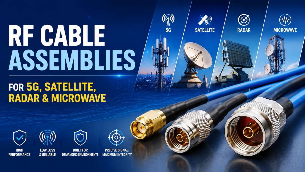
The cable assembly is where good RF systems quietly go wrong. You can spec a state-of-the-art radio, an LNA with a noise figure that took two years to design, or a phased-array module worth more than most cars, and then hand all that performance back to the room because the interconnect was chosen from a catalog. The interconnect is a system component. It has a link budget cost, a phase cost, a PIM cost, a lifetime cost. Get it right and it disappears from your problem list. Get it wrong and you spend the next twelve months chasing intermittents.
This is a working guide to picking RF cable assemblies for four applications where the stakes are highest: 5G infrastructure, satellite communications, radar systems, and microwave and mmWave test. Same physics, four very different sets of constraints.
On This Page
- Six Criteria That Apply to Every RF Cable Decision
- 5G: Low Loss, Low PIM, Outdoor Durability
- Satellite: Phase Stability and Extreme Environments
- Radar: Coherence, Ruggedness, and Phase Matching
- Microwave and Test: Precision Above 18 GHz
- Application-by-Application Comparison
- Practical Decision Framework
- Specification Mistakes That Cost Programs
- Frequently Asked Questions
- Bottom Line
Six Criteria That Apply to Every RF Cable Decision
Before any application-specific talk, six parameters set the frame. Miss any of them and you are guessing regardless of what industry you build for.
01
Frequency and attenuation
Loss climbs with frequency and length. A cable that hits budget at 3.5 GHz can be unusable at 28 GHz.
02
Impedance and VSWR
50 ohms almost always. Typical acceptance limits are VSWR under 1.25:1 or 1.35:1 across the operating band.
03
Phase stability
Critical whenever multiple channels must stay coherent: MIMO, phased arrays, interferometric radar.
04
Power handling
Both continuous-wave and peak power, with derating for altitude and temperature. Do not spec at the datasheet limit.
05
Environment and durability
Temperature range, UV, moisture, salt fog, vibration, flex life. Match the jacket and connector to the environment.
06
PIM performance
Dominant in multi-carrier cellular and high-power satellite uplink. Sample testing is not enough for infrastructure.
Now the four applications, each with different weights on those six axes.
5G: Low Loss, Low PIM, Outdoor Durability
Modern 5G runs across sub-6 GHz (FR1) and millimeter-wave (FR2), and the interconnect problem hides in two places: between remote radio units (RRUs) and the antennas above them, and inside DAS and small-cell installations where dozens of assemblies share a small volume.
What matters most for 5G is not attenuation alone. It is the combination of low loss, low PIM, and honest environmental durability. The single most common specification error in cellular deployment is picking cable purely on attenuation at 3.5 GHz and treating PIM as a footnote. In a dense urban site with multiple carriers, that cable will desense the uplink and the site will underperform against its design plan.
Key requirements
- Low insertion loss to preserve link budget on tower and rooftop runs
- Low PIM, typically -150 dBc to -165 dBc or better (measured at 2 × 43 dBm)
- UV-resistant, weatherproof jackets
- Weatherproof connectors: N-Type, 4.3-10, or 7/16 DIN
- Mechanical robustness against wind-induced vibration and temperature cycling
Typical construction
- Low-loss foam-dielectric flexible cable (LMR-400 class or equivalent)
- Specialized low-PIM constructions with solid or flat-braid outer conductors for outdoor jumpers
- Smaller-diameter low-PIM assemblies with 4.3-10 for indoor and plenum runs
- 100 percent PIM tested, with results marked on each assembly
Satellite: Phase Stability and Extreme Environments
Satellite work splits into two very different problems. Ground-segment terminals sit on the earth and behave like enterprise microwave systems with better weatherproofing. Flight hardware, whether LEO, MEO, or GEO, lives in vacuum, in radiation, and cannot be repaired.
Ground segment
Ground feeds use low-loss flexible or semi-rigid microwave cable terminated with precision N-Type, SMA, or 2.92 mm connectors. On the receive path, insertion loss is the enemy: every dB you lose in the feed is a dB added to the noise figure of everything downstream. On the transmit path, power handling and thermal management drive the choice.
Flight hardware
Space adds two hard constraints on top of everything else: phase stability across temperature, and material outgassing. Standard PTFE has a well-known phase versus temperature "knee" near room temperature that shifts the electrical length of the cable measurably. On a phased-array payload or an interferometer, that shift wrecks calibration. Specialized low-density or proprietary PTFE dielectrics reduce phase drift to a few hundred ppm or less across -55 to +125 °C. Phase-matched sets are commonly specified to ±1° to ±2° at the operating frequency.
Space-grade documentation checklist
- ● Lot traceability tied to specific manufacturing records
- ● Material certifications for cable, connectors, and solder
- ● ASTM E595 outgassing compliance (TML under 1 percent, CVCM under 0.1 percent)
- ● Thermal vacuum test data where required
- ● Radiation-hardness assessment for the mission profile
- ● Phase versus temperature data across the operating range
- ● Individual test data per assembly (not typical curves)
Specify Once, Test Every Assembly
SigmaRF builds low-PIM cellular jumpers, phase-matched radar sets, space-qualified microwave assemblies, and precision mmWave test cables. Every assembly is individually swept for VSWR and insertion loss before it ships, with the documentation your program actually needs.
Request a Quote →Radar: Coherence, Ruggedness, and Phase Matching
Radar systems, especially active electronically scanned arrays (AESA) and multi-channel pulsed radars, place the tightest phase-stability demands you will meet outside a metrology lab. A cable that drifts in electrical length with temperature or bending directly corrupts beamforming, raises sidelobes, and degrades target tracking. The radio does everything right and the interconnect steals it back.
Key requirements
- Phase stability vs temperature better than a few ppm/°C
- Phase stability vs flexure tightly controlled and specified in degrees at max frequency
- Excellent shielding effectiveness to prevent channel-to-channel coupling
- Survivable under MIL-STD-810 vibration and shock profiles
- Verified peak and average power handling
- Altitude derating for airborne platforms
Typical construction
- Factory-formed 0.085" or 0.141" semi-rigid inside radar LRUs
- High-performance phase-stable flexible where flex is required
- Low-density PTFE or proprietary dielectrics
- Phase-matched multi-channel sets with tracking data
- SMA, SMP, or 2.92 mm connectors, matched to the frequency
Multi-channel sets are almost never ordered as individual cables. They come as phase-matched kits with documented electrical-length matching data, so the array behaves at deployment the same way it did on the alignment bench.
Microwave and Test: Precision Above 18 GHz
General microwave systems and test benches (VNAs, signal generators, spectrum analyzers, component characterization) live and die by VSWR, insertion loss, and how repeatable the cable is across mating cycles. Frequency coverage runs to 18 GHz for older gear, 26.5 GHz for precision SMA and 3.5 mm, 40 GHz for 2.92 mm, 50 GHz for 2.4 mm, and 67 GHz for 1.85 mm.
Above 18 GHz, the connector becomes as consequential as the cable. Standard SMA does not hold spec cleanly, and precision 3.5 mm, 2.92 mm, 2.4 mm, or 1.85 mm interfaces take over. Armored or ruggedized microwave cable is preferred for production and field use because it resists crush and abrasion while keeping electrical length stable. Laboratory-grade phase-stable and amplitude-stable test cables come with actual measured data, not typical curves.
Application-by-Application Comparison
| Application | Primary Cable Type | Critical Parameters | Typical Connectors |
|---|---|---|---|
| 5G outdoor jumpers | Low-loss / low-PIM flexible | Attenuation, PIM ≤ -150 dBc, UV resistance | 4.3-10, N-Type, 7/16 DIN |
| 5G indoor / DAS | Low-PIM smaller-diameter flex | PIM, weight, plenum rating | 4.3-10, N-Type |
| Satellite ground segment | Low-loss flexible or semi-rigid | Loss, power handling, weather sealing | N-Type, SMA, 2.92 mm |
| Satellite flight hardware | Phase-stable space-qualified | Phase vs temp, outgassing, radiation | Precision microwave (SMA, 2.92 mm) |
| Phased-array radar | Phase-stable flexible or semi-rigid | Phase matching, shielding, vibration | SMA, SMP, 2.92 mm |
| Airborne radar | Semi-rigid or ruggedized flex | Vibration, altitude derating, phase | SMA, SMP, 2.92 mm |
| Microwave test up to 40 GHz | Low-loss phase-stable armored | VSWR, flex life, mating cycles | 3.5 mm, 2.92 mm |
| mmWave test 40 to 67 GHz | Precision microwave / semi-rigid | VSWR, amplitude stability | 2.4 mm, 1.85 mm |
Practical Decision Framework
When you are evaluating a supplier proposal (or writing your own spec), work through these seven items in order. Anything left blank is where the project will bite you later.
Step 01
Confirm the highest operating frequency and total loss budget
Include connectors. Two connectors and an adapter can easily contribute 0.3 dB or more to the budget.
Step 02
Determine whether phase matching is required
If yes, specify the tolerance in degrees at the highest frequency and require documented tracking data.
Step 03
Mandate low-PIM and 100 percent PIM test for multi-carrier work
Insist on per-assembly test data marked on the assembly. Sample testing is not adequate for infrastructure.
Step 04
Match jacket and connector to the environment
Outdoor UV, plenum-rated, marine, shipboard, airborne, space. Each has specific material and rating requirements.
Step 05
Verify power handling with proper derating
Both peak and average power, with altitude and temperature derating. Do not run at the datasheet limit.
Step 06
Require full test data and traceability for high-reliability programs
Certificate of Conformance, material certs, individual test data, lot traceability. Do not accept "typical" curves as delivered data.
Step 07
Evaluate total cost of ownership, not sticker price
A modestly more expensive assembly that avoids field failures, truck rolls, and recalibration is almost always cheaper across a five-year deployment.
Specification Mistakes That Cost Programs
- ✗ Specifying 5G jumpers on attenuation alone and ignoring PIM. Uplink desense will follow.
- ✗ Accepting sample PIM test data on multi-carrier infrastructure. Every jumper needs individual data.
- ✗ Using standard PTFE cable in phased-array radar and finding out about the phase knee during environmental test.
- ✗ Ordering satellite flight cable without ASTM E595 outgassing certification.
- ✗ Running SMA at 26 GHz in a 5G FR2 test setup instead of moving to 3.5 mm or 2.92 mm.
- ✗ Buying individual cables for a phased-array system that should have been ordered as a phase-matched set.
- ✗ Treating "typical" datasheet curves as delivered performance data.
- ✗ Skipping altitude derating on airborne radar power calculations.
- ✗ Optimizing for unit price and paying for it in truck rolls and recalibrations.
Frequently Asked Questions
What is the best RF cable for 5G base stations?
For outdoor jumpers between remote radio units and antennas, low-loss low-PIM flexible cable in the LMR-400 class (or specialized low-PIM equivalents) with 4.3-10 or N-Type connectors is the standard choice. Insist on 100 percent PIM testing with results marked on each assembly. For indoor DAS and small-cell work, smaller-diameter low-PIM assemblies with 4.3-10 connectors reduce weight and tower loading.
What PIM level should I specify for 5G cable assemblies?
Typical infrastructure specifications call for -150 dBc to -165 dBc or better, measured at 2 × 43 dBm. The tighter the PIM number, the better the multi-carrier uplink behaves. Always require the test to be per-assembly, not per-lot sample.
Why does phase stability matter in radar cables?
Radar systems rely on precise phase alignment between channels to form beams and reject clutter. If the electrical length of a cable drifts with temperature or flexure, the phase at the antenna element drifts with it. That drift raises sidelobes, degrades target tracking, and undoes calibration. Phase-stable construction with low-density PTFE or proprietary dielectrics reduces this to a few ppm per °C.
What is a phase-matched cable set?
A phase-matched set is a group of cables built and tested together so that their electrical lengths track within a specified tolerance, usually ±1° to ±2° at the operating frequency. Phased arrays, MIMO systems, and interferometric radar all require them. Every set ships with tracking data proving the match.
What cable is used for satellite ground stations?
Low-loss flexible cable (LMR-400 class or larger low-loss constructions) or semi-rigid microwave cable, terminated with precision N-Type, SMA, or 2.92 mm connectors depending on frequency. The receive-path priority is low insertion loss to protect noise figure; the transmit-path priority is power handling.
Do satellite RF cables need special dielectric?
Yes, for flight hardware. Standard PTFE has a phase versus temperature "knee" near room temperature that shifts electrical length measurably, which corrupts calibration in phased-array payloads and interferometers. Specialized low-density PTFE or proprietary fluoropolymer dielectrics reduce the drift to a few hundred ppm across -55 to +125 °C.
Which connector do I need for 40 GHz test work?
2.92 mm (also called K connector). It holds spec cleanly to 40 GHz and mates with SMA and 3.5 mm connectors, which makes it the go-to microwave test interface in labs that also work at lower frequencies.
What's the difference between LMR-400 and low-PIM cable?
LMR-400 (and equivalents) is a low-loss flexible cable family. Low-PIM cable is any construction specifically engineered and tested to keep passive intermodulation below a specified level. A cable can be low-loss without being low-PIM. For 5G infrastructure you need both.
Do I need semi-rigid cable for radar systems?
For fixed internal routing inside a radar LRU where phase stability is critical, yes. Factory-formed semi-rigid gives the best combination of low loss, shielding, and geometric stability. Where flexure or serviceability is required, high-performance phase-stable flexible cable is used instead.
Bottom Line
RF cable assemblies are not commodities. In 5G they are the difference between a healthy uplink and a desensed one. In satellite they are the difference between a phased array that calibrates and one that never does. In radar they are the difference between beamforming that works and beamforming that drifts. In microwave test they are the difference between measurements you can defend and measurements you cannot.
Match the assembly to the physics of the application. Quantify the loss budget, phase requirements, PIM targets, power handling, and environmental stresses before you look at any catalog. Insist on measured data per assembly, not typical curves. Then buy the cable that actually meets the spec, not the one that comes closest at the lowest unit price. Every RF engineer who has ever chased a mysterious field failure knows why this matters.
Application-Matched RF Cable Assemblies
Low-PIM 5G jumpers with 4.3-10, N-Type, and 7/16 DIN connectors. Phase-matched radar sets with SMA, SMP, and 2.92 mm. Space-qualified satellite assemblies. Precision mmWave test cables with 2.4 mm and 1.85 mm. Every assembly individually tested with delivered data.
Standard Assemblies Custom Assemblies Talk to an Engineer- Why Cheap RF Cable Assemblies Fail: Construction Shortcuts and How to Spot Them
- Solving Antenna Range Loss on an IoT Device: A Worked Diagnostic Example
- SMA Mating Cycles: How Many Connections Can an SMA Survive?
- RG58 Attenuation: Datasheet Specs vs Real-World Loss
- VNA Testing for Cable Assemblies: How VSWR and Insertion Loss Verification Works
- How a Custom Coaxial Cable Assembly Is Built, Step by Step
- Cellular Repeater and DAS Cable Selection: In-Building Coverage Guide
- Wi-Fi HaLow (802.11ah): Sub-GHz Wi-Fi and Its Antenna/Cable Needs
- RF Interconnects for Test Labs: Building a Reliable VNA Bench
- Direct-to-Cell Satellite and IoT: What It Means for Ground Hardware