RF Cable Assembly Design Guide: PCB to Antenna Reliability
Published on 7/31/2026 • Updated on 7/31/2026
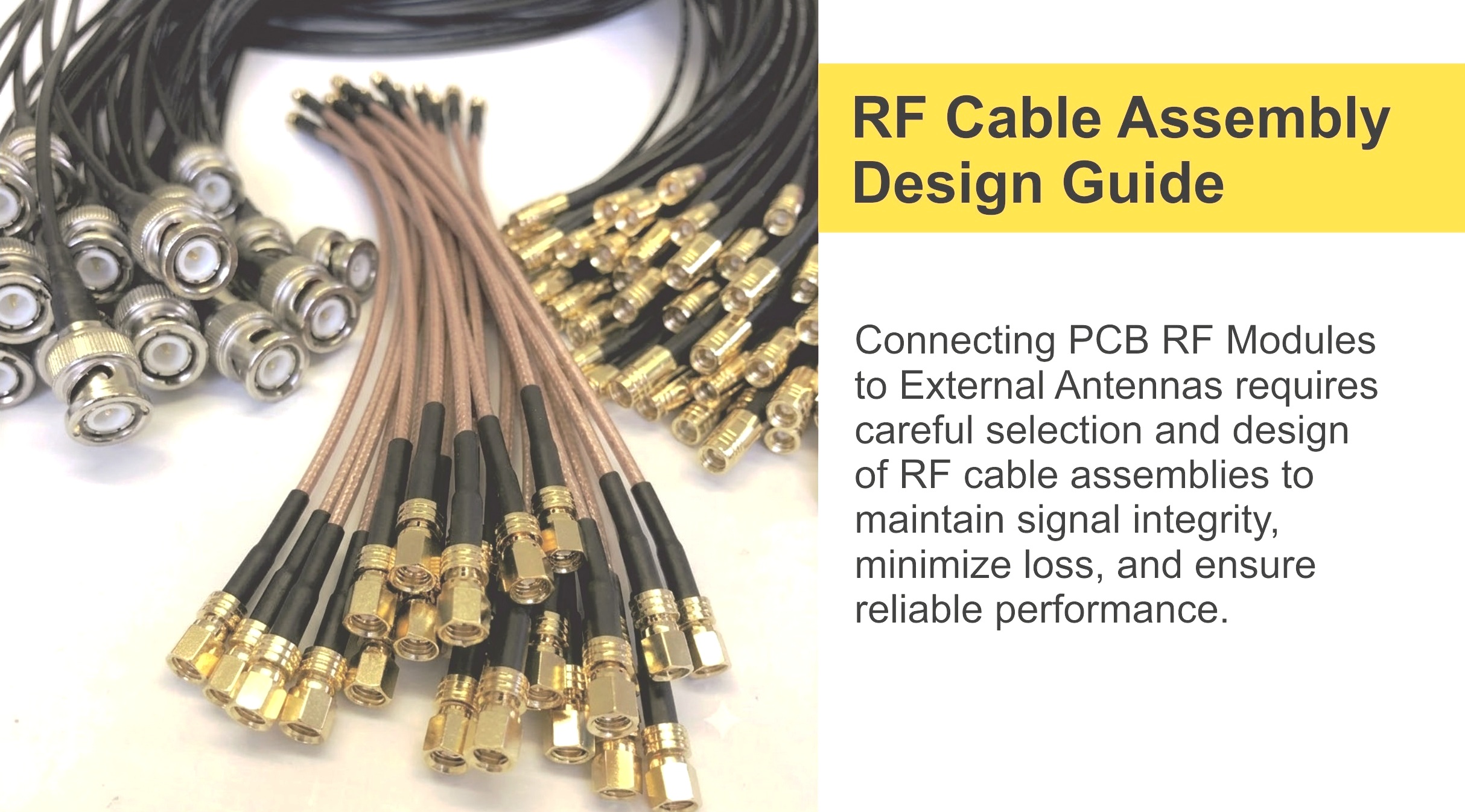
The pattern behind most of them is the same. The PCB was asked to carry both the RF signal and the mechanical load from the external antenna. It handled the RF fine. It couldn't handle the mechanical load. Given enough torque cycles, vibration, or careless field service, something in the connector interface eventually gives up.
The fix is a design philosophy, not a component swap. Let the enclosure absorb the mechanical stress and let the PCB just carry the signal. Get that architecture right and the product ships reliably. Get it wrong and you spend the second half of the product's life chasing intermittent RF problems that turn out to be mechanical.
On This Page
- The Core Design Principle
- Why PCB-Mounted RF Connectors Actually Fail
- The Bulkhead-Anchored Architecture
- Designing the PCB Launch
- Board-Side Connectors and Locking Variants
- The Pigtail as a Mechanical Isolator
- Choosing the Bulkhead Connector
- Grounding: Metal vs Plastic Enclosures
- Sealing for Outdoor and IP-Rated Products
- Vibration, Shock, and Environmental Testing
- Torque Values Every Assembly Needs
- Routing Rules That Save Assemblies
- Off-the-Shelf vs Custom at Production Scale
- Failure Modes This Approach Prevents
- Frequently Asked Questions
- Bottom Line
The Core Design Principle
One sentence. Learn it, apply it, and half the RF reliability problems in embedded products disappear.
Everything downstream in this article is an implementation of that principle. The external antenna connection is mounted to the enclosure, not the PCB. A short coaxial pigtail bridges the gap between the enclosure-mounted connector and the module's RF pin. All the torque from tightening an antenna, all the vibration transmitted through the housing, all the pull force from someone stepping on the antenna cable, gets absorbed by the mechanical structure of the enclosure. None of it reaches the PCB. The board just sees a well-behaved RF signal at a small board-level connector that will never be mated by the end user.
The alternative (mounting an SMA directly to the PCB and letting the user thread an antenna onto it) is not automatically wrong. On small products with light antennas, low vibration, and no user-serviceable antenna, it can work fine for the product's lifetime. But it's the design that fails hardest when the assumptions break down. Which they usually do.
Why PCB-Mounted RF Connectors Actually Fail
Understanding the failure mechanism helps you spec the fix correctly. Here's what physically happens when a PCB-mounted SMA fails.
Every SMA torque is a lateral force on the connector body. The correct spec is 5 in-lb (0.56 Nm), but hand-torqued connectors often see 8 to 15 in-lb, especially when installers are trying to make sure the antenna is "really tight." That force translates into a shear stress at the solder joints holding the connector to the PCB. A single event doesn't cause a problem; the joint is elastic within limits. Repeated events (unscrewing to swap antennas, retightening after they loosen, vibration, thermal cycling) fatigue the solder.
Typical failure sequence:
Stage 1: hairline solder crack
A microcrack appears at the highest-stress corner of the connector's largest solder joint (usually where the ground shield meets the PCB). Not visible under normal inspection. Electrical connection still intact but resistance rises slightly.
Stage 2: crack propagation
Subsequent torque cycles extend the crack across the joint. Occasional intermittent contact under vibration. VSWR drifts up. Field techs call it "flaky" and blame the antenna.
Stage 3: pad delamination
Copper pad separates from the FR4 substrate. Typical PCB pull strength is around 4 to 8 pounds before delamination; a torqued SMA generates that easily. Now the joint is open circuit or high resistance. RF link drops.
Stage 4: connector wobbles
Mechanically loose. Any further attempt to torque an antenna onto it tears the remaining connections. Board is scrap.
Stages 1 and 2 can span months or years. By the time Stage 3 hits, the product has usually shipped, the failure looks intermittent, and the root cause (mechanical fatigue from field service) is hard to reproduce on the bench. This is the classic "works in the lab, fails in the field" pattern.
The Bulkhead-Anchored Architecture
Once you know how the failure happens, the fix is obvious. Move the mechanically loaded connector off the PCB entirely and anchor it to the enclosure. The signal path becomes:
↓
Board-level connector (U.FL / MHF 4 / MMCX)
permanently mated, never touched after assembly
↓
Short coaxial pigtail (100 to 200 mm)
absorbs all mechanical stress
↓
Bulkhead connector (mounted to enclosure wall)
the mechanical anchor
↓
External antenna (mates with bulkhead)
Every mechanical force that used to reach the PCB now stops at the bulkhead. The board just sees a small, permanently mated board-level connector at one end of a well-supported pigtail. Nothing on the PCB has to survive the user tightening the antenna, dropping the product, or vibrating in a truck for five years.
This is the architecture used in essentially every professionally-designed IoT gateway, cellular router, industrial telemetry unit, GNSS receiver, and vehicle telematics product on the market. It's not because the designers can't figure out how to mount an SMA directly to the board. It's because they figured out (usually the hard way, once) that this architecture doesn't come back as a field return.
Designing the PCB Launch
The PCB layout at the RF connector is where a lot of "small" impedance problems hide. Get this right and the assembly measures well. Get it wrong and you spend the rest of the project chasing VSWR spikes at specific frequencies.
The trace from the RF chip pin to the board-level connector must maintain 50 ohms across the operating band. On typical FR-4 (dielectric constant around 4.3) with a 0.2 mm PCB, that's a microstrip trace roughly 0.35 mm wide, or a coplanar-waveguide-with-ground trace slightly narrower with careful ground clearance. Real values depend on your stack-up; use a controlled-impedance calculator (or ask your PCB fab for their impedance charts) rather than eyeballing it.
Practical rules for the RF launch on the PCB:
- ✓ Keep the RF trace as short as possible. Every millimeter of trace is a millimeter of potential impedance discontinuity.
- ✓ Stitch the ground plane with vias every quarter-wavelength along the trace. At 5 GHz that's about 15 mm in FR-4; more often is better.
- ✓ Provide a continuous return path. The ground under the RF trace must not be interrupted by other signal traces or split planes.
- ✓ Avoid stubs at the connector. Any unused trace or via at the launch is a resonant stub that shows up as a VSWR spike.
- ✓ Include a matching network footprint (a pi or T with 0402 components) between the module and the connector, even if you don't populate it. Manufacturing tolerances mean you may need one later.
- ✓ Keep the RF chip's ground pins bonded to the ground plane with multiple vias directly under the pad. Ground return inductance kills chip performance.
- ✓ Add mounting holes near the board connector for a stiffener bracket if the assembly will see vibration. Sometimes the connector is fine but the PCB flexes.
Reference: IPC-2141 covers controlled-impedance PCB design, and IPC-2221 covers general PCB design practice. Most fab houses provide impedance charts specific to their stack-ups. Use them.
Board-Side Connectors and Locking Variants
The board-side of the pigtail should be a small, low-loss connector that's mated once at assembly and never touched again. Common choices, sized to the module:
| Connector | Retention Force | Max Frequency | Where It Fits |
|---|---|---|---|
| U.FL / MHF I | ~2 N | 6 GHz | ESP32, small IoT modules, general use |
| MHF I LK (locking) | ~15 N | 6 GHz | Vibration environments, automotive, industrial |
| MHF 4 | ~3 N | 15 GHz | Modern M.2 Wi-Fi 6E / 7, LTE, 5G modules |
| MHF 4 LK (locking) | ~20 N | 15 GHz | Automotive telematics, aviation, ruggedized |
| MMCX | ~10 N (snap) | 6 GHz | Repeated mating, industrial, medical |
| Edge-launch SMA | Threaded | 18 GHz | When the board itself is user-facing (dev kits, panels) |
The locking variants (MHF I LK, MHF 4 LK, and equivalents like W.FL LP from other manufacturers) are worth knowing about. A standard U.FL retains at roughly 2 N of pull force, which is fine for a static assembly but fails under vibration in automotive, aerospace, or industrial environments. The locking variants use a small metal detent that engages on mating and requires a specific unlock action to remove; retention jumps to 15 to 20 N. If your product will see vibration testing to IEC 60068 or MIL-STD-810, spec the locking variant.
The Pigtail as a Mechanical Isolator
The coax between the board connector and the bulkhead is doing more than carrying RF. It's the mechanical decoupling element between two rigid subassemblies. Its ability to flex slightly under thermal expansion, vibration, and enclosure assembly is what protects both the board connector and the bulkhead from stress transfer.
This changes the selection criteria in subtle ways:
- Length: enough slack to accommodate assembly tolerance and thermal movement, but not so much that the cable coils and pinches. 100 to 200 mm covers most enclosures. Extreme designs go shorter with specialized cable; extreme designs go longer with heavier cable.
- Cable choice: 1.13 mm micro-coax is the compact default. RG-178 is a step up in ruggedness for harsher environments. RG-316 is chosen when the pigtail runs long or through a hostile environment. For very high-cycle products (dev kits, test equipment), RG-316 with quality connectors lasts longer than any micro-coax construction.
- Bend radius: micro-coax typically needs at least 5 mm bend radius for full life, and can accept 3 mm as an absolute minimum. RG-178 and RG-316 want 10 to 15 mm minimum.
- Strain relief: heat-shrink at the board connector transition and a proper strain relief boot at the bulkhead protect the assembly from concentrated stress at the mechanical interfaces.
- Ground path: the pigtail's outer conductor is the RF return path from bulkhead to PCB. On plastic enclosures, it's the only return path. Damaged shield or corroded connectors here can degrade the whole system.
Custom Pigtail Assemblies with Locking Micro-Coax
SigmaRF builds pigtails with U.FL, MHF I LK, MHF 4 LK, MMCX, and edge-launch SMA at the board end; SMA, RP-SMA, N-Type, and TNC bulkhead configurations in straight or right-angle, bulkhead, 2-hole flange, or 4-hole flange styles. Individually swept for VSWR and insertion loss before shipment.
Request a Custom Pigtail →Choosing the Bulkhead Connector
The bulkhead is the mechanical anchor. Its job is to survive whatever the user, the environment, and the operating conditions throw at it, and to transfer none of that stress to the PCB. Match it to the mechanical loading it will actually see.
| Style | Mechanical Load | IP Rating (typical) | Use For |
|---|---|---|---|
| Bulkhead (nut) | Light to moderate | IP54 to IP65 with O-ring | Indoor gateways, routers, IoT gear |
| 2-hole flange | Moderate to heavy | IP65 to IP67 with gasket | Industrial, medical, transportation |
| 4-hole flange | Heavy to extreme | IP67 or IP68 with proper sealing | Outdoor, marine, defense, railway |
Connector family is separate from the mounting style. SMA, RP-SMA, TNC, N-Type, and 4.3-10 all come in each of the three mounting variants. Pick the mounting for the mechanical load, and the family for the frequency, power, and mating requirement.
Grounding: Metal vs Plastic Enclosures
Grounding is where this architecture quietly succeeds or quietly fails. The rules are different depending on what your enclosure is made of.
Metal enclosure
The bulkhead body electrically bonds to the enclosure through the mounting nut or flange screws. The enclosure becomes an RF reference. Two things must be true:
- The PCB ground must be tied to the enclosure at low impedance, usually at multiple mounting standoffs with metal fasteners bonding into the ground plane.
- The enclosure surface where the bulkhead mounts must be clean of paint, oxidation, or anodizing that would isolate the bulkhead body from the metal.
If you skip either, the pigtail's shield tries to carry all the RF return current alone, which raises impedance and can generate common-mode currents that couple RF into other cables in the enclosure.
Plastic enclosure
The bulkhead body has no ground reference except through the pigtail's shield. This puts more demand on:
- The PCB ground plane, which is now the only ground reference for the whole RF system.
- The pigtail's shield integrity, which is the only path for the return current.
- The board connector's ground bond to the PCB (which is one of the joints most likely to fail mechanically).
Ground plane size on the PCB also becomes an antenna performance factor, since most Wi-Fi and cellular antennas assume a ground plane of at least a quarter wavelength on the side of the antenna.
Sealing for Outdoor and IP-Rated Products
If the product is going outdoors, the bulkhead is where water gets in. Every failure investigation on outdoor RF equipment eventually points at connector seals. The RF path may work perfectly for two years, then start showing high VSWR, and when you open the connector there's green corrosion on the contacts. This is one of the most common failure modes in outdoor telematics, cellular gateways, and IoT infrastructure.
The IP rating system (IEC 60529) is what you'll see in outdoor product specs:
| Rating | Water Protection Meaning | Typical Use |
|---|---|---|
| IP54 | Splash from any direction | Indoor industrial, sheltered outdoor |
| IP65 | Low-pressure water jets, dust-tight | Outdoor gateways, cellular equipment |
| IP66 | High-pressure water jets, dust-tight | Industrial outdoor, transportation |
| IP67 | Temporary immersion, 1 m for 30 min | Marine, defense, harsh outdoor |
| IP68 | Continuous submersion (per manufacturer) | Underwater, buried, sub-sea |
Two things matter for the bulkhead:
- The connector itself must have an O-ring or gasket rated to your target IP level. Standard commercial SMA is usually IP54 at best. N-Type is naturally more weather-resistant. 4.3-10 and 7/16 DIN with proper O-rings can achieve IP67 straight from the factory. Look for MIL-C-39012 or equivalent qualified parts for defense and aerospace.
- The mating interface (where the antenna threads onto the bulkhead) must also be sealed once installed. Self-amalgamating tape is the standard approach, wrapped over the mated connector after tightening. Some products use silicone boots or heat-shrink weatherproof kits (e.g., 3M CoAx-Seal).
A well-sealed installation lasts 10 to 15 years outdoors. A poorly-sealed one starts showing VSWR degradation in 12 to 24 months. This is not a small delta.
Vibration, Shock, and Environmental Testing
If your product will see certification testing, the standard you'll test to depends on the market:
| Standard | Application | What It Covers |
|---|---|---|
| MIL-STD-810 | Defense, aerospace, ruggedized commercial | Vibration, shock, temperature, altitude, salt fog, sand |
| IEC 60068 | Industrial and commercial equipment | Sinusoidal and random vibration, thermal shock |
| GR-63-CORE | Telecom infrastructure (US) | Physical protection, seismic, transport |
| ISO 16750 | Automotive electronics | Automotive vibration and mechanical shock |
| EN 50155 | Railway electronics | Vibration, shock, temperature for rolling stock |
The pattern engineering teams learn (usually after a first failed test) is that a PCB-mounted RF connector almost never passes MIL-STD-810 vibration for long, and a bulkhead-anchored assembly almost always does. If certification is in your future, design the RF interconnect for it from the start rather than trying to reinforce a PCB-mounted connector after it fails.
Two additional considerations for vibration:
- Use locking micro-coax (MHF I LK, MHF 4 LK) at the board end. Non-locking variants can walk off under sustained vibration.
- Provide strain relief at both ends of the pigtail. The stress raiser at the strain-relief-to-connector transition is where cables actually break under vibration.
Torque Values Every Assembly Needs
Hand-tight is not a specification. Threaded RF connectors have specific torque values, and both under-torque (leaks, drifts) and over-torque (damages contacts and dielectric) cause reliability problems. Use a calibrated torque wrench.
Reference torque values
3.5 mm / 2.92 mm precision: 8 in-lb (0.9 Nm)
2.4 mm / 1.85 mm precision: 8 in-lb (0.9 Nm)
TNC: 12 to 15 in-lb (1.4 to 1.7 Nm)
N-Type: 15 in-lb (1.7 Nm)
4.3-10: 44 in-lb (5 Nm)
7/16 DIN: 221 in-lb (25 Nm)
BNC: bayonet, hand-tight to locking position
Bulkhead mounting nuts are also torque-specific but rarely called out. For panel-mount SMA and RP-SMA, the mounting nut is typically 20 to 25 in-lb. Over-torquing here can crack the bulkhead body or deform the enclosure. Use a spanner wrench, not pliers.
Routing Rules That Save Assemblies
- ✓ Route the pigtail flat against the PCB near the board connector, so no leverage is applied at the mating interface.
- ✓ Keep RF cables at least 20 mm away from switching power supplies, DC motors, LCD backlights, and any other high dV/dt or dI/dt sources.
- ✓ Cross other cables at right angles rather than running parallel, if crossing is unavoidable.
- ✓ Never route the pigtail across enclosure seams, hinges, or removable panels where it can be pinched during assembly or service.
- ✓ Use soft cable ties or adhesive clips to fix the pigtail's path. Never use tight zip ties on micro-coax, they crush the dielectric.
- ✓ Provide a small service loop at each end so future rework doesn't tension the joints.
- ✓ For rotating antennas or hinged panels, use a pigtail rated for repeated flexure (some micro-coax variants specifically address this).
- ✓ Document the routing in the assembly drawing. Every subsequent assembly line worker needs to know where the cable actually goes.
Off-the-Shelf vs Custom at Production Scale
The prototype phase is fine on catalog pigtails. Grab a U.FL-to-SMA cable from a distributor, route it around, prove the concept. Production is a different question.
Custom pigtails pay for themselves at scale when you need:
- Precise length control: exact fit to your enclosure geometry, no coiled excess, cleaner assembly
- Uncommon connector combinations: MHF 4 LK to N-Type 4-hole flange in RG-316 with strain relief, for example
- Consistent electrical performance: every unit VNA-tested, insertion loss within tolerance, matched pairs for MIMO
- Enhanced strain relief: purpose-designed boots or overmolds where catalog cables have generic strain reliefs
- Ruggedization: extra shielding, tighter jacket materials, specific temperature ratings
- Traceability: serial numbers, test data with each assembly, audit trail for aerospace or medical
The economics usually cross over between 100 and 1000 units. Below that, catalog cables are fine and the labor of routing quirky lengths isn't worth the custom NRE. Above that, custom cables reduce assembly defects, reduce field returns, and often actually cost less per unit than catalog stock once you factor in the assembly labor saved by not having to route excess cable.
Failure Modes This Approach Prevents
The bulkhead-anchored architecture, done properly, eliminates the common field failures that plague RF products:
- ✗ Cracked solder joints and lifted pads under board-mounted SMA connectors after repeated antenna service
- ✗ Side-loaded U.FL connectors that lift off the board during first field service
- ✗ Micro-coax damage from enclosure assembly pinch points and screws
- ✗ Intermittent RF contact under vibration from unsupported connector transitions
- ✗ Ground path discontinuities at the enclosure-to-PCB interface
- ✗ Water ingress at bulkhead interfaces on outdoor products
- ✗ VSWR drift over the product's life from mechanical fatigue in the RF path
- ✗ Failed vibration certification testing (MIL-STD-810, IEC 60068, ISO 16750)
- ✗ Cascading enclosure damage when a broken bulkhead pulls PCB pads and traces with it
Frequently Asked Questions
Can I mount an SMA connector directly to my PCB?
You can, and for small products with light antennas that will not be user-serviced, it usually works fine. The failure mode appears when antenna torque, vibration, or field service applies repeated mechanical load to the connector. Solder joints fatigue and pads eventually delaminate. The safer architecture for anything that will see field service or vibration is a bulkhead-mounted connector anchored to the enclosure, with a short pigtail to the PCB.
What is a locking U.FL / MHF connector?
A variant of the U.FL or MHF family with a small metal detent that engages on mating and requires a specific unlock action to remove. I-PEX calls them MHF I LK and MHF 4 LK; other manufacturers have equivalent products (W.FL LP, GSC-LOC). Retention force jumps from 2 to 3 N (standard) to 15 to 20 N (locking). Use them in automotive, industrial, aerospace, or any product that will be vibration-tested to MIL-STD-810 or IEC 60068.
How do I ground the RF path in a plastic enclosure?
In a plastic enclosure the bulkhead has no metallic ground reference, so all RF return current flows through the pigtail's shield to the PCB ground plane. The PCB ground plane becomes the primary ground reference. Make sure the plane is continuous under the RF trace, generous in area (many small antennas want at least a quarter-wavelength of ground plane on the side of the antenna), and bonded solidly to the board connector's ground pins with multiple vias. Shield damage or high-impedance joints anywhere in this path will degrade both RF performance and EMC.
What torque should I use for an SMA connector?
5 in-lb (0.56 Nm) for both standard SMA and RP-SMA. Use a calibrated torque wrench. Under-torque leaks RF and drifts under vibration; over-torque damages the center contact and can crack the dielectric. Hand-tightening typically ends up somewhere between 8 and 15 in-lb, which is why hand-torqued SMAs often fail long-term. For precision connectors (3.5 mm, 2.92 mm, 2.4 mm, 1.85 mm), the spec is 8 in-lb (0.9 Nm).
What IP rating do I need for an outdoor product?
IP65 is the minimum for a genuinely outdoor product; IP67 is preferred for anything that might see prolonged rain, snow, or washdown. The bulkhead itself needs an O-ring or gasket rated to your target level, and the mated interface with the antenna needs weatherproofing (self-amalgamating tape or a sealing boot) applied at install. N-Type and 4.3-10 connectors seal more reliably than SMA. Do not assume "IP-rated enclosure" means "IP-rated at the connector"; the bulkhead is the failure point.
Does the PCB layout at the RF connector really matter?
Yes. The trace from the RF chip to the connector needs to be 50 ohms, with continuous ground return, no stubs, and ground vias every quarter-wavelength to keep the return path low-impedance. A layout mistake at the launch shows up as a VSWR spike that no amount of external tuning fixes. Reference IPC-2141 for controlled-impedance design and use your PCB fab's impedance charts to pick trace widths for your stack-up.
When should I switch from catalog pigtails to custom?
The crossover is usually between 100 and 1000 units. Below that, catalog cables are fine and the setup cost of custom parts isn't worth it. Above that, custom pigtails typically reduce assembly time (right length, right routing), reduce assembly defects (proper strain relief), and produce lower field-return rates. They also make traceability possible for aerospace, medical, and defense customers who need documented performance per unit.
How do I test my RF interconnect design before production?
Three levels. First, VNA-sweep the assembly to verify insertion loss and VSWR across the operating band. Second, run a mating cycle test (repeatedly connect and disconnect the antenna 100 to 500 times, then re-sweep). Third, run environmental testing appropriate for your product (thermal cycling, vibration to your target standard, and IP-rating water tests). Field-representative testing catches the mechanical failures that pure electrical measurement misses.
Bottom Line
The RF cable assembly is a mechanical part as much as an electrical one. The failures that hit RF products in the field are overwhelmingly mechanical: fatigued solder joints, side-loaded connectors, moisture in bulkheads, ground paths that opened up under vibration. All of these are preventable at design time by anchoring the mechanically-loaded connector to the enclosure and using a short, well-supported pigtail to reach the PCB.
Get the PCB launch layout right, use locking micro-coax where vibration is a factor, pay attention to grounding for your enclosure material, seal the bulkhead properly for outdoor use, torque every threaded connector to spec, and route the pigtail so it never sees leverage at either connector. Consider custom assemblies once you're past prototype, both for consistency and for eliminating the field return rate that catalog assemblies quietly rack up over years.
Do all of that and the RF interconnect stops being your problem. Skip any of it and it becomes the reason your product has a 3 percent field return rate that you can't explain until you FMEA an actual returned unit and find that the SMA joint cracked six months ago.
Reliability-Focused RF Assemblies from SigmaRF
Custom pigtails with locking micro-coax (MHF I LK, MHF 4 LK), bulkhead, 2-hole flange, and 4-hole flange configurations, IP67-sealed variants for outdoor deployment, and matched sets for MIMO. Every assembly individually VNA-tested for VSWR and insertion loss, with traceable serial numbers and test data shipped alongside.
Standard Assemblies Custom Assemblies Talk to an Engineer- Why Cheap RF Cable Assemblies Fail: Construction Shortcuts and How to Spot Them
- Solving Antenna Range Loss on an IoT Device: A Worked Diagnostic Example
- SMA Mating Cycles: How Many Connections Can an SMA Survive?
- RG58 Attenuation: Datasheet Specs vs Real-World Loss
- VNA Testing for Cable Assemblies: How VSWR and Insertion Loss Verification Works
- How a Custom Coaxial Cable Assembly Is Built, Step by Step
- Cellular Repeater and DAS Cable Selection: In-Building Coverage Guide
- Wi-Fi HaLow (802.11ah): Sub-GHz Wi-Fi and Its Antenna/Cable Needs
- RF Interconnects for Test Labs: Building a Reliable VNA Bench
- Direct-to-Cell Satellite and IoT: What It Means for Ground Hardware