Shielding Effectiveness in RF Cable Assemblies Explained
Published on 7/27/2026 • Updated on 8/1/2026
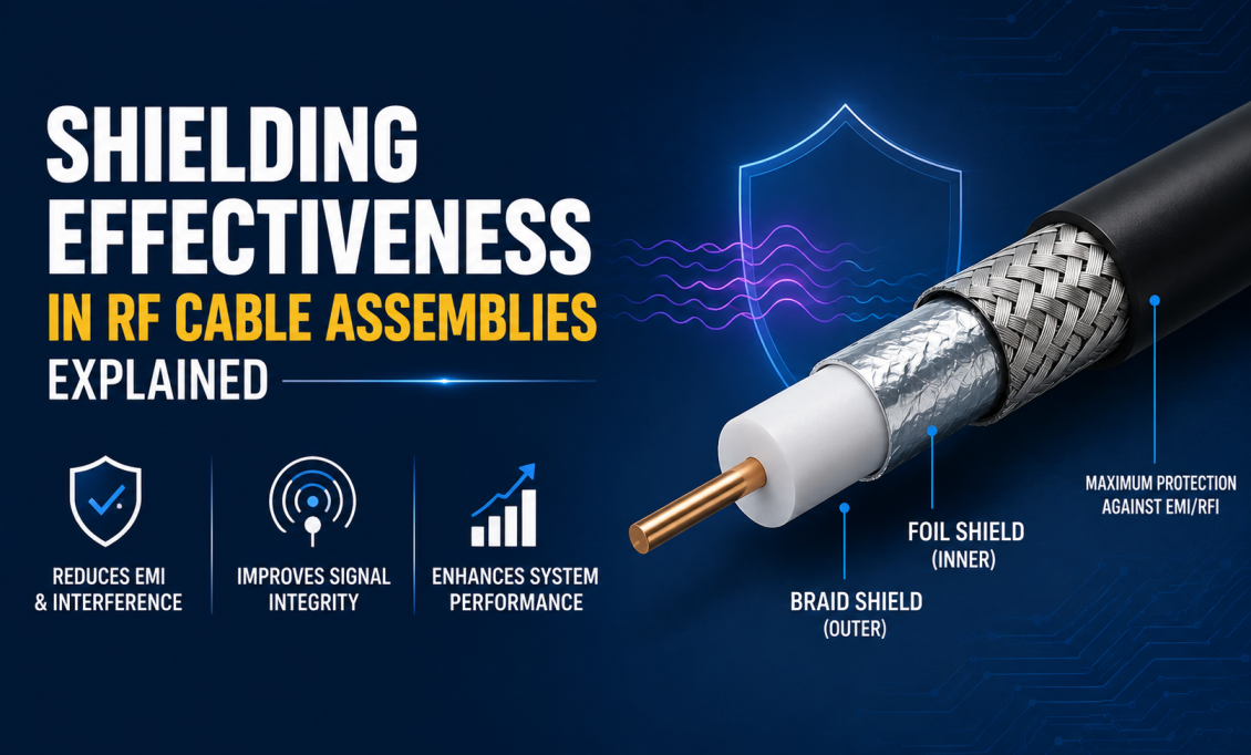
The outer conductor of a coaxial cable has two jobs, and they are the same job seen from two sides. It has to keep the RF signal inside the cable so it does not leak out and radiate. And it has to keep external RF energy from getting in and corrupting the signal. Both jobs matter, and how well a cable does them is captured in a single number: shielding effectiveness, measured in decibels.
At sub-GHz frequencies you can get away with a lot. At microwave and mmWave, you cannot. A cable with mediocre shielding will show up as a noise floor that is a few dB higher than it should be, as channel-to-channel crosstalk in a multi-radio system, as PIM products on cellular uplinks, and as radiated emissions that fail EMC testing. Every one of those problems has been chased by an engineer who assumed the interconnect was clean.
This guide covers what shielding effectiveness actually is, how the four cable families compare, and how to pick a shield architecture that matches your system.
On This Page
- What Shielding Effectiveness Really Means
- Why It Matters at High Frequencies
- Reading Shielding Effectiveness in dB
- The Four Cable Families Compared
- RG-Series Cables
- LMR and Low-Loss Flexible Cables
- Semi-Rigid Cables
- Rigid Coaxial Lines
- Side-by-Side Shielding Comparison
- How to Select the Right Cable
- The Connector Is Part of the Shield
- Installation Practices That Preserve Shielding
- Maintenance and Service Life
- Application-Specific Recommendations
- Common Shielding Mistakes
- Frequently Asked Questions
- Bottom Line
What Shielding Effectiveness Really Means
Shielding effectiveness (SE) is the ratio of RF energy hitting one side of the shield to the energy that makes it through to the other side, expressed in dB. If a shield lets one-millionth of the incident energy pass, that is 60 dB of shielding. One-billionth is 90 dB. Every extra 10 dB means ten times better isolation.
The number goes both directions. The shield that keeps your RF signal from leaking outward is the same shield that keeps external interference from leaking inward. So when you specify SE, you are simultaneously specifying two things: how much your cable can radiate before it becomes an EMC problem, and how much external EMI the cable can absorb before it becomes a noise-floor problem.
Why It Matters at High Frequencies
At low frequencies, most shields look pretty solid. A basic braid on an RG-58 gives you 55 to 60 dB, and for a lot of RF work that is fine. The trouble starts as frequency climbs and the physics changes.
Two things happen. First, the skin effect drives the RF current into a very thin layer on the inside of the outer conductor. That layer becomes electrically important, and any interruption in it (a gap in the braid weave, an oxidized strand, a connector interface with a poor ground) starts to look like an antenna. Second, the wavelength of the signal gets smaller. At 10 GHz the wavelength in air is 30 mm; at 40 GHz it is 7.5 mm. Braid gaps that were electrically invisible at 100 MHz are efficient radiators at 40 GHz.
This is why the same cable, tested at different frequencies, will show different SE numbers. Almost every SE spec on a datasheet will be for a specific frequency or frequency band. Compare like with like.
Reading Shielding Effectiveness in dB
A working sense of what the numbers actually mean helps a lot when reading datasheets.
| Shielding | Fraction of Energy Blocked | Typical Cable Type |
|---|---|---|
| 40 dB | Blocks 99.99% | Cheap single braid, low grade |
| 60 dB | Blocks 99.9999% | Typical single-braid RG |
| 80 dB | Blocks 99.999999% | Good double-braid RG |
| 100 dB | Blocks 99.99999999% | LMR / low-loss foil-plus-braid |
| 120+ dB | Essentially perfect | Semi-rigid, rigid, solid outer conductor |
Note that 20 dB is not a small difference. Going from 60 dB to 80 dB means the shield now leaks 100 times less energy. Going to 100 dB is 10,000 times less. That is why the choice of shield architecture is not incremental. It is a set of very different tiers.
The Four Cable Families Compared
Almost every coaxial cable you will meet fits into one of four construction families. Each has a fundamentally different shield architecture and a fundamentally different SE ceiling.
RG-Series Cables
The RG-series names go back to the U.S. military RG (Radio Guide) numbering system: RG-58, RG-174, RG-316, RG-142, RG-213, and the rest. Modern RG cables use a single or double braided shield of tinned or silver-plated copper, typically at 85 to 95 percent coverage. That is the crux of the shielding limitation. There are always gaps in a braid weave, even a good one. Every gap is a small leak, and the leaks add up.
Strengths
- Flexible, easy to route
- Inexpensive, widely stocked
- Adequate for short internal jumpers
- Good enough for HF, VHF, UHF work
Limitations
- Single braid SE typically 55 to 75 dB
- Double braid SE typically 75 to 90 dB
- Braid leakage rises with frequency
- Not suitable for dense EMI environments
RG cables are the right answer for short lab jumpers, short internal chassis wiring, low-frequency test setups, and any application where extreme isolation is not required. Above a few GHz or in a dense EMI environment, the residual leakage becomes the limiting factor and you should be looking at LMR-class or better.
LMR and Low-Loss Flexible Cables
Modern low-loss families (LMR-195, LMR-240, LMR-400 and equivalents from other manufacturers) fundamentally rethink the shield architecture. Instead of a single or double braid, they use a two-layer construction: a solid aluminum foil bonded to the dielectric, plus a tinned-copper braid over the foil.
The foil gives you 100 percent physical coverage against high-frequency leakage. The braid gives you mechanical strength and better performance at low frequencies where the thin foil alone starts to become resistive. Combined, they push shielding effectiveness to 90 to 100 dB and often better. This is why LMR-class cable is the default for outdoor 5G jumpers, cellular infrastructure, satellite ground segment, and most radar and communications ground applications.
Strengths
- Shielding 90 to 100+ dB
- Low insertion loss (foam dielectric)
- UV-resistant outdoor jackets
- Still flexible for field installation
- Excellent value for cellular and satellite ground
Limitations
- Foil cracks if bent tighter than min radius
- Not phase-stable enough for phased arrays
- Larger diameter than equivalent RG
- Not sufficient shielding for high-density mmWave
Semi-Rigid Cables
Semi-rigid takes the shield architecture to its logical extreme: replace the braid entirely with a solid metal tube (copper, tin-plated copper, sometimes aluminum). Because the outer conductor is now continuous metal with no gaps of any kind, shielding effectiveness routinely exceeds 120 to 140 dB across the full microwave range. There is nothing for RF to leak through.
Common diameters are 0.085", 0.141", and 0.250" (referenced by outer conductor OD). The trade-off is mechanical. Once formed, the shape is permanent. You cannot flex a semi-rigid repeatedly without work-hardening the tube and cracking it. That is why semi-rigid dominates inside radar modules, aerospace electronics bays, and high-isolation microwave instruments where the cable will be shaped once at manufacture and never moved again.
Rigid Coaxial Lines
True rigid coaxial lines are two concentric metal tubes with dielectric spacers holding them in precise alignment. Diameters run from under an inch to more than 8 inches. Shielding effectiveness is essentially perfect. The only leakage paths are at the connector interfaces and expansion joints, and those are engineered to minimize it.
This is not a general-purpose cable. It is used for high-power broadcast transmitters, radar feeders, cellular tower trunk runs, and other applications where power handling and lowest possible loss dominate. Direction changes require machined elbows, tees, and transitions. You do not "install" a rigid coax line the way you install a flexible one. You build it, piece by piece.
Every Shield Architecture, Tested Before It Ships
SigmaRF builds cable assemblies across the full shielding spectrum: RG single- and double-braid for lab work, LMR-class low-loss for cellular and outdoor, semi-rigid 0.085" and 0.141" for microwave systems, and specialized low-PIM constructions for 5G infrastructure. Each assembly individually swept for VSWR and insertion loss.
Get a Custom Assembly →Side-by-Side Shielding Comparison
| Cable Type | Shield Architecture | Typical SE | Flex Life | Best For |
|---|---|---|---|---|
| RG single braid | Tinned/silver copper braid | 55 to 75 dB | Excellent | Lab jumpers, sub-GHz work |
| RG double braid | Two braids over dielectric | 75 to 90 dB | Excellent | Improved shielding without going to LMR |
| LMR / low-loss | Foil bonded to dielectric + braid | 90 to 100+ dB | Good | Cellular, 5G, satellite ground, outdoor |
| Semi-rigid | Solid copper or tin-plated tube | 120 to 140+ dB | One form, permanent | Radar modules, mmWave, aerospace |
| Rigid coax | Two concentric tubes, spacers | Essentially perfect | Fixed installation | Broadcast, radar feeders, tower trunk |
How to Select the Right Cable
Six questions get you 90 percent of the way to the right cable. Answer them before you look at any datasheet.
Question 01
What is the highest operating frequency and loss budget?
Higher frequency needs both lower cable loss and better shielding. LMR-400 at 3.5 GHz is fine; at 40 GHz it is unusable.
Question 02
What shielding effectiveness do you actually need?
For quiet lab environments, 60 to 80 dB is fine. For dense EMI or multi-channel work, target 100 dB and above. For anything mission-critical or above 20 GHz, aim higher.
Question 03
Does the cable need to flex?
Repeated flexure rules out semi-rigid and rigid. If flex is required, RG or LMR with attention to bend radius is the answer.
Question 04
Is phase stability required?
Phased arrays and interferometric systems need semi-rigid or specialized phase-stable flex. Standard LMR will not hold phase across temperature.
Question 05
What is the environment?
Outdoor, marine, aerospace, space, indoor lab. Each has different jacket, connector, and shielding-degradation exposures. Match the whole cable to the environment, not just the electrical spec.
Question 06
What power level?
Both CW and peak. At kilowatt levels you need rigid or large-diameter corrugated cable, not flexible. Do not run at the datasheet limit.
The Connector Is Part of the Shield
This is the section most articles skip. It matters more than any of the cable choices.
A cable with 120 dB shielding effectiveness terminated in a connector with 60 dB isolation is a 60 dB system. You built a nickel wall around a hole. Every SE spec you read is meaningful only if the connectors, the connector-to-cable attachment, and the mating interfaces preserve it.
Practical implications:
- ✓ Match the connector's shielding to the cable's. Do not put a low-cost commercial SMA on a semi-rigid microwave assembly.
- ✓ The connector-to-cable interface (crimp, solder, or clamp) is a common leak. Factory-terminated assemblies are more repeatable than field terminations.
- ✓ Threaded connectors (SMA, N-Type, TNC) hold shielding better than snap-on (MCX, MMCX) under vibration.
- ✓ Every adapter in a chain adds interfaces. Two adapters back-to-back can drop system shielding effectiveness noticeably.
- ✓ Corrosion at outdoor connector interfaces destroys shielding faster than the cable ages. Seal them.
Installation Practices That Preserve Shielding
The best cable you can buy will not deliver its rated shielding if it is installed badly. A few habits worth having:
- ✓ Respect the minimum bend radius. Sharp bends crack foil, distort braid, and misalign the center conductor.
- ✓ Support the cable at intervals so the connectors do not carry weight or vibration.
- ✓ Torque threaded connectors to spec with a calibrated wrench. SMA at 5 in-lb (0.56 Nm), N-Type at 15 in-lb (1.7 Nm). Under-torque leaks. Over-torque damages contacts.
- ✓ Weatherproof outdoor connector interfaces with self-amalgamating tape or approved sealing boots. Water in a connector destroys shielding through corrosion.
- ✓ Do not use tight cable ties that crush the jacket and shield. Use wide, soft supports.
- ✓ Maintain physical separation between assemblies that must not couple, or add external shielding.
- ✓ Keep semi-rigid cables in the exact form they left the factory. Do not re-bend.
Maintenance and Service Life
A well-installed cable assembly with quality connectors will typically deliver 10 to 25 years of service. The exact number depends on environment more than anything else.
| Environment | Typical Service Life | Limiting Factor |
|---|---|---|
| Indoor lab or equipment bay | 15 to 20+ years | Connector mating cycles |
| Outdoor cellular / broadcast | 10 to 15 years | UV, thermal cycling, moisture |
| Airborne / vehicle | 10 to 15 years | Vibration, temperature |
| Space (LEO/MEO/GEO) | Mission life | Radiation, outgassing, thermal |
| High-cycle test cables | Months to a few years | Connector wear from mating |
Basic maintenance that adds years to the number:
- Periodic visual inspection for jacket cracks, abrasion, or connector corrosion
- Clean connector interfaces with isopropyl alcohol and lint-free swabs. Never touch mating surfaces with bare fingers
- Verify connector pin depth with a gauge after every 100 or so mating cycles, or whenever performance degrades
- Replace any assembly with permanent kinks, crushed sections, or rising VSWR or insertion loss
- Retorque threaded connectors that have loosened due to vibration
The connectors are usually what limit the life of an assembly, not the cable itself. A high-cycle test cable may need replacement after a few thousand matings; a fixed semi-rigid inside a benign enclosure can last decades.
Application-Specific Recommendations
| Application | Recommended Cable | Shielding Priority |
|---|---|---|
| 5G and cellular infrastructure | LMR / low-PIM foil-plus-braid | 100 dB+ and low PIM |
| Radar and phased-array | Semi-rigid or phase-stable flex | 120 dB+ for channel isolation |
| Satellite ground segment | LMR-class or semi-rigid | 100 dB+ with weather sealing |
| Satellite flight hardware | Phase-stable space-qualified | 120 dB+ with outgassing compliance |
| Test and measurement | Ruggedized phase-stable flex | 100 to 120 dB, stable across cycles |
| High-power transmitter feeders | Rigid or corrugated | Essentially perfect |
| Dense electronic enclosures | Semi-rigid or double-braid | 100 dB+ to control internal EMI |
| Lab jumpers, sub-GHz work | RG single or double braid | 60 to 80 dB is usually enough |
Common Shielding Mistakes
- ✗ Assuming a datasheet SE number applies at all frequencies. It almost always does not; check the test frequency.
- ✗ Buying premium cable and terminating it with commercial connectors. The connectors set the ceiling.
- ✗ Bending LMR-class cable tighter than the minimum radius. Cracked foil is invisible from outside and destroys shielding.
- ✗ Using single-braid RG in a dense EMI environment and blaming the radio for a high noise floor.
- ✗ Ignoring the connector interface torque. Under-torque leaks; over-torque damages.
- ✗ Skipping the weatherproofing on outdoor connectors. Moisture ingress destroys shielding faster than any electrical failure.
- ✗ Stacking adapters instead of ordering the correct assembly. Every interface leaks.
- ✗ Field-terminating cable when the assembly needs to hold spec. Factory-terminated is more repeatable.
Frequently Asked Questions
What is shielding effectiveness in RF cables?
Shielding effectiveness (SE) is a measure, in decibels, of how well a cable's outer conductor prevents RF energy from leaking in or out. 60 dB means the shield blocks 99.9999 percent of the incident energy; 100 dB means it blocks 99.99999999 percent. Higher is better, but the number also depends on the frequency at which it was measured.
What is a good shielding effectiveness value for RF cable?
For general lab work at low frequencies, 60 to 80 dB is usually sufficient. For cellular and satellite ground applications, target 100 dB or more. For radar, mmWave, dense EMI environments, and multi-channel systems, aim for 120 dB and above, which typically requires semi-rigid or specialized foil-plus-braid construction.
Why does shielding matter more at higher frequencies?
Two reasons. The skin effect drives RF current into a very thin layer on the inside of the outer conductor, so any interruption in that layer becomes electrically significant. And the wavelength gets smaller, which means small physical gaps in a braid weave become efficient antennas. A cable rated to 60 dB at 100 MHz can easily drop to 30 dB at 10 GHz.
What is the difference between single-braid, double-braid, and foil-plus-braid shielding?
Single braid is one layer of woven conductor around the dielectric, giving 55 to 75 dB SE. Double braid stacks two layers, reaching 75 to 90 dB. Foil-plus-braid uses a solid aluminum foil bonded to the dielectric plus a copper braid over it, delivering 90 to 100+ dB by combining foil's 100 percent coverage with braid's low-frequency performance and mechanical strength.
Does semi-rigid coax really shield better than LMR?
Yes. Semi-rigid replaces the braid or foil with a continuous solid metal tube, so there are no gaps at all. Shielding effectiveness routinely exceeds 120 to 140 dB across microwave frequencies. LMR-class cables top out around 100 to 110 dB because there is always some residual coupling through the braid weave.
Do connectors affect shielding effectiveness?
Yes, significantly. The connector interface and the connector-to-cable attachment are common leakage points. A cable with 120 dB SE terminated in a poorly-shielded connector is limited by the connector, not the cable. Always match connector quality to cable shielding, torque threaded connectors correctly, and weatherproof outdoor interfaces.
How long does an RF cable assembly last?
A well-installed assembly with quality connectors typically delivers 10 to 25 years of service. Indoor lab and equipment bay assemblies often exceed 15 to 20 years. Outdoor cellular and broadcast installations are limited to 10 to 15 years by UV, thermal cycling, and moisture. High-cycle test cables may need replacement after a few thousand mating cycles because the connectors wear out.
Can I improve shielding on an installed cable?
Not really. You cannot improve the shield architecture of an existing cable. What you can do: replace poorly torqued connectors, weatherproof exposed interfaces, remove adapter chains, or add external shielding (conduit, ferrite, EMI enclosure) around a run that is coupling badly. Beyond that, if the cable's SE is insufficient for the job, replace it with a better-shielded construction.
Is high shielding effectiveness always better?
Not for every application. Higher SE usually means less flexible cable, higher cost, and often larger diameter. For a short lab jumper at 500 MHz, 60 dB is fine and paying for 120 dB is money you did not need to spend. Match the shielding to the requirement, not to the datasheet's biggest number.
Bottom Line
Shielding effectiveness is not a secondary spec at high frequencies. It is the difference between a cable that behaves like a transmission line and one that behaves like an antenna. Choose the shield architecture (single braid, double braid, foil-plus-braid, semi-rigid, or rigid) that matches the isolation your system actually needs, and match the connector quality to it. Torque properly, weatherproof outdoors, respect the bend radius, and inspect periodically.
Do those things and the cable assembly disappears from your problem list. Which, for RF hardware, is the highest compliment you can pay it.
RF Cable Assemblies with the Shielding You Need
From single-braid RG for lab work to semi-rigid microwave assemblies with 130 dB shielding for radar and mmWave. SigmaRF individually tests every assembly for VSWR and insertion loss, terminated with SMA, N-Type, TNC, BNC, 4.3-10, 3.5 mm, 2.92 mm, and precision microwave connectors.
Standard Assemblies Custom Assemblies Talk to an Engineer- Why Cheap RF Cable Assemblies Fail: Construction Shortcuts and How to Spot Them
- Solving Antenna Range Loss on an IoT Device: A Worked Diagnostic Example
- SMA Mating Cycles: How Many Connections Can an SMA Survive?
- RG58 Attenuation: Datasheet Specs vs Real-World Loss
- VNA Testing for Cable Assemblies: How VSWR and Insertion Loss Verification Works
- How a Custom Coaxial Cable Assembly Is Built, Step by Step
- Cellular Repeater and DAS Cable Selection: In-Building Coverage Guide
- Wi-Fi HaLow (802.11ah): Sub-GHz Wi-Fi and Its Antenna/Cable Needs
- RF Interconnects for Test Labs: Building a Reliable VNA Bench
- Direct-to-Cell Satellite and IoT: What It Means for Ground Hardware