RF Cable Signal Loss and Attenuation: Complete Engineer's Guide
Published on 7/28/2026 • Updated on 8/1/2026
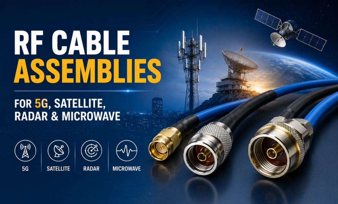
Every RF cable loses signal. That is not a defect. It is physics, and it is the single most consequential engineering choice you make on any RF link. Whether you are running a 5G rooftop jumper, wiring a satellite ground station, building a radar test bench, or just installing a Wi-Fi antenna at the far end of a warehouse, the cable is quietly deciding how much of your transmitter power reaches the antenna, and how much of your antenna's received signal ever makes it back to your receiver.
A dB feels small until you calculate what it costs you. Two dB of extra loss on a receive path is a real bite out of your noise figure. Six dB on a transmit path means three-quarters of your PA output is heating the cable. Do this on a link that was already marginal and the link stops working, sometimes intermittently, sometimes for good.
This guide walks through what actually causes signal loss in coaxial cable, how much each mechanism contributes, and how experienced RF engineers spec cable assemblies to keep loss under control.
On This Page
- What Signal Loss Actually Is
- Why Every dB Matters
- Reading dB: What the Numbers Mean
- Loss Cause 1: Conductor Loss and the Skin Effect
- Loss Cause 2: Dielectric Loss
- Loss Cause 3: Shield Loss and Leakage
- Loss Cause 4: Connector and Adapter Loss
- Loss Cause 5: Cable Length
- Loss Cause 6: Operating Frequency
- Loss Cause 7: Cable Diameter
- Loss Cause 8: Impedance Mismatch
- Loss Cause 9: Mechanical Damage
- Loss Cause 10: Moisture Ingress
- RF Cable Loss Comparison
- Worked Example: Calculating Total Link Loss
- How to Reduce RF Cable Loss
- Common Loss Mistakes
- Frequently Asked Questions
- Bottom Line
What Signal Loss Actually Is
Signal loss in a coaxial cable, also called attenuation or insertion loss, is the reduction in RF power as the signal travels from one end of the cable to the other. Some of the energy heats the copper. Some of it heats the dielectric. A tiny amount radiates out through imperfections in the shield. What arrives at the far end is always less than what was launched.
Attenuation is expressed in decibels, normalized against length. You will see it three ways on datasheets:
- dB per meter (most common in modern datasheets)
- dB per 100 feet (traditional US usage, still common in cellular)
- dB per 100 meters (favored for long runs and comparison)
Why Every dB Matters
Every dB of loss cuts your available RF power. The math is not linear, and this is where the intuition trips people up. Three dB is not "a little bit." Three dB is half your power gone.
| Cable Loss | Power That Reaches the Antenna | What It Feels Like on a Link |
|---|---|---|
| 0.5 dB | 89% | Barely noticeable |
| 1 dB | 79% | Acceptable for most links |
| 2 dB | 63% | Starts to bite into link margin |
| 3 dB | 50% | Half your power gone |
| 6 dB | 25% | Range effectively halved |
| 10 dB | 10% | Only a tenth reaches the antenna |
| 20 dB | 1% | The link is basically broken |
And this cuts both ways. Loss on the receive path directly worsens the effective noise figure of the front end. A 3 dB feeder loss between the antenna and the LNA is 3 dB added to your noise figure. That LNA you spent months tuning to 0.6 dB now looks like 3.6 dB to the rest of the system. All that engineering, given back to the cable.
Reading dB: What the Numbers Mean
A few dB rules of thumb every RF engineer keeps in their head:
dB Cheat Sheet
−6 dB = quarter power
−10 dB = one-tenth power
−20 dB = one-hundredth power
−30 dB = one-thousandth power
Because dB is logarithmic, losses simply add. A 20-meter run of cable with 0.15 dB/m attenuation is 3 dB of loss. Add a connector at each end (say 0.15 dB each) and the total is 3.3 dB. Add an adapter (another 0.15 dB) and you are at 3.45 dB. That is 45 percent of your power heating things rather than radiating.
Loss Cause 1: Conductor Loss and the Skin Effect
Conductor loss is usually the biggest contributor to cable attenuation, and it gets worse with frequency. At DC, RF current uses the full cross-section of the wire. At RF, current concentrates near the outer surface of the conductor in a thin skin. The effective conducting area shrinks. Resistance rises. More energy turns into heat.
This is the skin effect, and it is why a cable that measures 0.05 dB/m at 100 MHz can measure 0.5 dB/m at 10 GHz. Some real numbers for the skin depth in copper:
| Frequency | Skin Depth in Copper | Effect on Loss |
|---|---|---|
| 100 MHz | ~6.6 µm | Modest |
| 1 GHz | ~2.1 µm | Significant |
| 10 GHz | ~0.66 µm | Dominant contributor |
| 28 GHz (5G mmWave) | ~0.39 µm | Runs entirely in the plating |
Above 1 GHz, the RF signal is running in a layer thinner than most conductor plating. This is why silver-plated conductors matter (silver has better conductivity than copper) and why surface roughness starts to add real loss at mmWave.
Loss Cause 2: Dielectric Loss
The dielectric is the insulating material between the center conductor and the outer shield. It has to hold precise dimensions to maintain 50 ohms of characteristic impedance, and it has to do that with as little RF absorption as possible.
Common choices, roughly in order of best RF performance:
Best
Low-density PTFE / air-spaced
Lowest RF loss, phase stable, expensive. Used in semi-rigid microwave, phase-stable flex, and premium test cables.
Good
Solid PTFE (Teflon)
Very low RF loss, thermally stable to +200 °C, standard on mil-spec and aerospace cable.
Mid
Foam polyethylene
Low loss, cost-effective. Standard on LMR-class low-loss cellular and outdoor cable.
Higher loss
Solid polyethylene / FEP
Higher RF loss, lower cost. Common on classic RG-series and inexpensive commercial cable.
Dielectric loss becomes a bigger fraction of total attenuation at higher frequencies. This is why premium test cables spec low-density PTFE and why microwave semi-rigid designs care so much about dielectric quality.
Loss Cause 3: Shield Loss and Leakage
The outer conductor of a coaxial cable has to complete the transmission line's return path and contain the signal. If the shield is incomplete, leaky, or corroded, some RF energy leaves the cable entirely and never reaches the far end. That is loss you cannot get back.
Shield construction, roughly in order of quality:
- Single braid (60 to 90 percent optical coverage): the classic RG shield
- Double braid: better than single, still has weave gaps
- Foil-plus-braid: aluminum foil for 100 percent coverage plus braid for mechanical strength (standard on LMR-class)
- Corrugated solid copper: used in cellular tower feeders
- Solid copper tube: semi-rigid microwave, essentially zero leakage
This is a topic worth its own article; if you want the details of shielding effectiveness in dB, when to move from RG to LMR to semi-rigid, and how connectors play into it, we cover it in depth in our dedicated shielding effectiveness guide.
Loss Cause 4: Connector and Adapter Loss
Even a great cable can be undone by cheap or badly installed connectors. Every connector introduces a small insertion loss from contact resistance, mechanical tolerances, and the impedance transition at the interface. A properly torqued, high-quality connector is negligible. A cross-threaded, dirty, or wrong-family connector is not.
| Connector | Typical Insertion Loss | Notes |
|---|---|---|
| N-Type | 0.05 to 0.15 dB | Excellent to 11 GHz, larger geometry helps |
| SMA | 0.1 to 0.2 dB | Fine to 18 GHz, higher losses above that |
| TNC | 0.1 to 0.2 dB | Similar to BNC, threaded coupling |
| BNC | 0.1 to 0.3 dB | Higher above 1 GHz, avoid at microwave |
| 3.5 mm / 2.92 mm | Under 0.1 dB | Precision microwave to 26.5 / 40 GHz |
| 2.4 mm / 1.85 mm | Under 0.1 dB | Precision mmWave to 50 / 67 GHz |
| 4.3-10 / 7/16 DIN | Under 0.1 dB | Cellular infrastructure, low PIM |
Adapters add roughly the same insertion loss as a connector each. This is why chaining three adapters together to solve a mating problem is bad practice. It is 0.3 to 0.45 dB of loss on paper, and often more in reality because the VSWR contributions from each interface combine unpredictably. Order the correct assembly and skip the chain.
Loss Cause 5: Cable Length
Length is the one variable you often have most control over. Attenuation scales linearly with length: if a cable has 0.15 dB/m loss, then 10 m is 1.5 dB, 30 m is 4.5 dB, and 100 m is 15 dB.
Two practical implications:
- Keep runs as short as physically possible without stressing the cable at the connectors
- For long runs, spend the money on lower-loss cable up front; the cost per dB saved over the cable's lifetime is small
Loss Cause 6: Operating Frequency
Higher frequency means more loss. It shows up in three ways at once: skin effect makes the conductor look thinner, the dielectric absorbs a larger fraction of the RF energy, and surface roughness on the conductor begins to matter. The result: cable loss at 10 GHz is typically three to five times cable loss at 1 GHz for the same construction.
Loss Cause 7: Cable Diameter
Larger-diameter cables have lower loss. The center conductor has more surface area (which matters because of the skin effect), the outer conductor has better shielding, and the geometry is generally more forgiving. The trade-off is weight, cost, bend radius, and connector size.
Typical loss ranking, worst to best, for equivalent constructions:
RG174 RG316 RG58 RG400 LMR-195 LMR-240 LMR-400 LMR-600
Loss Cause 8: Impedance Mismatch
If the source, cable, connectors, and load do not all share the same characteristic impedance, part of the RF signal reflects back toward the transmitter instead of reaching the load. That reflected power appears as additional loss on your link, and it drives up VSWR.
In practice:
- 50 ohms: wireless communications, test equipment, radar, satellite, cellular. This is the default for RF work.
- 75 ohms: television, satellite receive, broadcast video, CATV.
- Do not mix them in the same path. Even a short 75 ohm cable in a 50 ohm system is a problem, and forcing a 75 ohm F-Type onto a 50 ohm N-Type mating surface is worse.
Loss Cause 9: Mechanical Damage
A coaxial cable depends on precise spacing between the center conductor and outer shield. Anything that changes that spacing changes the local impedance, which creates a reflection, which shows up as additional loss and higher VSWR.
Common causes:
- Bending tighter than the minimum bend radius
- Crushing under weight or foot traffic
- Tight cable ties that pinch the jacket and dielectric
- Stretching or pulling with the cable in tension
- Kinking at connector strain relief points
Damage is often invisible from the outside. A cable that looks fine can be 1 to 3 dB worse than spec because of a kink you cannot see.
Loss Cause 10: Moisture Ingress
Water in an RF cable is a slow disaster. Moisture changes the effective dielectric constant, corrodes the shield braid, and creates a growing spot of localized loss and reflection. Even a small amount of ingress can add 1 to 5 dB of loss over months, and it will get worse until you replace the assembly.
Weatherproof every outdoor connector. Self-amalgamating tape, approved sealing boots, drip loops so water does not run into the interface. This is the single biggest cause of premature outdoor cable failure.
Low-Loss Cable Assemblies, Tested Before They Ship
SigmaRF builds cable assemblies from RG316 pigtails to LMR-400 outdoor jumpers to semi-rigid microwave cable at 40 GHz. Every assembly is individually swept for VSWR and insertion loss at your operating band before it leaves the factory.
Get a Custom Assembly →RF Cable Loss Comparison
Typical attenuation for common cable types at three frequencies (approximate, dB per meter). Real values vary by manufacturer; check the datasheet for your specific part.
| Cable | Loss @ 900 MHz | Loss @ 2.4 GHz | Loss @ 5.8 GHz | Typical Use |
|---|---|---|---|---|
| RG174 | ~0.60 | ~1.10 | ~1.80 | Very short internal pigtails |
| RG316 | ~0.55 | ~0.95 | ~1.55 | Test leads, short jumpers |
| RG58 | ~0.35 | ~0.60 | ~1.05 | General-purpose RF |
| RG400 | ~0.30 | ~0.55 | ~0.90 | Aerospace, mil-spec, lab |
| LMR-195 | ~0.25 | ~0.45 | ~0.75 | Wi-Fi, small-cell jumpers |
| LMR-240 | ~0.20 | ~0.35 | ~0.55 | Cellular indoor, medium runs |
| LMR-400 | ~0.13 | ~0.22 | ~0.35 | 5G outdoor jumpers, cellular |
| LMR-600 | ~0.09 | ~0.15 | ~0.25 | Long tower runs, base stations |
Worked Example: Calculating Total Link Loss
Let us walk through a real cellular install and calculate the actual insertion loss on the link. Assume a 25-meter run from a remote radio unit to a rooftop antenna at 2.4 GHz. You have two options:
Option A: RG58 with N-Type connectors
Connector loss: 2 × 0.10 dB = 0.2 dB
Total: 15.2 dB
Power reaching antenna: about 3 percent of transmitter output
Option B: LMR-400 with N-Type connectors
Connector loss: 2 × 0.10 dB = 0.2 dB
Total: 5.7 dB
Power reaching antenna: about 27 percent of transmitter output
Going from RG58 to LMR-400 saves you 9.5 dB, which is roughly a 9-times improvement in delivered power. And this cuts both ways: on the receive path, the LMR-400 install has 9.5 dB better sensitivity too. That is the difference between a link that works reliably and one that drops calls at the cell edge.
The LMR-400 cable costs more up front. Over the life of the site, it is cheaper.
How to Reduce RF Cable Loss
- ✓ Keep cable runs as short as physically practical. Every meter counts.
- ✓ Spec low-loss cable for anything above a few meters at GHz frequencies. LMR-400 class or better.
- ✓ Silver-plated conductors help significantly above 1 GHz. Below that, the improvement is small.
- ✓ Minimize connector transitions. Every connector is 0.1 to 0.2 dB even at its best.
- ✓ Delete adapter chains. Two adapters is 0.3 dB you did not need to spend. Order the correct assembly.
- ✓ Match impedance rigorously. Never mix 50 and 75 ohm in the same path.
- ✓ Respect the minimum bend radius. Sharp bends create local impedance mismatch and hidden loss.
- ✓ Torque every connector to spec with a calibrated wrench.
- ✓ Weatherproof every outdoor connector with self-amalgamating tape or approved boots.
- ✓ Inspect installed cable periodically for jacket damage, corrosion at connectors, or rising VSWR.
Common Loss Mistakes
- ✗ Comparing cables at 100 MHz datasheet values and assuming they still apply at 5 GHz.
- ✗ Using RG58 or RG316 for a 20-meter outdoor cellular run because it was in stock.
- ✗ Stacking three adapters instead of ordering the correct assembly.
- ✗ Coiling excess cable into tight loops that pinch the dielectric.
- ✗ Skipping the weatherproofing on outdoor connectors and letting moisture rot the shield.
- ✗ Assuming a 75 ohm cable "will probably work" in a 50 ohm system.
- ✗ Blaming the antenna for range problems that are actually 8 dB of feeder loss.
- ✗ Ignoring cable damage that "looks fine" but has been crushed under equipment.
Frequently Asked Questions
What causes signal loss in RF coaxial cables?
RF signal loss (attenuation) comes from four main mechanisms: conductor loss caused by the skin effect, dielectric absorption in the insulator, shield leakage, and connector interface loss. Length, frequency, cable diameter, impedance mismatch, mechanical damage, and moisture ingress all affect how much loss the cable actually delivers in your system.
Why does higher frequency mean more cable loss?
Three things happen at once. The skin effect drives RF current into a thinner and thinner surface layer, so effective resistance rises. Dielectric materials absorb more energy per meter. And surface roughness on the conductor starts to matter. Together they mean cable loss at 10 GHz is typically three to five times higher than at 1 GHz for the same construction.
How much loss does 3 dB actually represent?
3 dB is exactly half the power. If you launch 100 watts into a cable with 3 dB of loss, 50 watts reach the far end. 6 dB is a quarter, 10 dB is one-tenth, and 20 dB is one-hundredth of the original power.
Is LMR-400 low-loss?
Yes, at cellular and Wi-Fi frequencies. Typical LMR-400 loss is about 0.13 dB/m at 900 MHz, 0.22 dB/m at 2.4 GHz, and 0.35 dB/m at 5.8 GHz. That is significantly better than any RG-series cable of similar diameter and makes it the default choice for outdoor cellular jumpers and Wi-Fi antenna runs.
Does a thicker cable always have lower loss?
For the same construction quality, yes. Bigger cable means more conductor surface area for RF current, better shielding, and better heat handling. The trade-offs are weight, cost, bend radius, and connector size. Larger cable is standard on long runs; smaller cable is fine on short jumpers.
Can connector quality really affect RF cable performance?
Yes, significantly. Poorly installed or damaged connectors introduce reflections, add insertion loss, and create impedance discontinuities that degrade the whole system. Cheap SMA on premium cable is limited by the SMA. Correctly torqued precision connectors are essentially invisible.
Is cable loss more important than antenna gain?
Cable loss directly reduces the power available to the antenna, so on marginal links it often matters more than incremental antenna gain. Upgrading a lossy feeder from 8 dB to 3 dB gives you 5 dB improvement on both transmit and receive. Adding 3 dBi of antenna gain only helps on transmit. In many real installs, fixing the cable is the higher-value change.
How do I calculate total RF cable loss for my link?
Add the cable loss (loss per meter times length at your operating frequency) to the insertion loss of every connector, adapter, and lightning protector in the path. Everything adds in dB. For quick estimates: cable loss dominates on long runs, connector count dominates on short assemblies with lots of interfaces.
What is a good insertion loss for a coaxial cable?
There is no universal "good" number because it depends on frequency and length. As rules of thumb: for a short lab jumper, aim for under 0.5 dB total. For a rooftop cellular install, aim for under 3 dB. Above 5 dB the link starts to hurt badly. Above 10 dB you are losing 90 percent of your power and should redesign.
Does silver plating reduce RF cable loss?
Yes, above about 1 GHz, where the skin effect drives the RF signal into a thin surface layer that is entirely within the plating. Silver has better conductivity than copper, so silver plating lowers surface resistance and cuts loss. At 28 GHz, silver plating versus tin plating can save 0.8 to 1.5 dB per meter. Below 500 MHz, the benefit shrinks because the current uses the copper underneath too.
Bottom Line
Signal loss in RF cable is not one thing. It is ten things acting at once: skin-effect conductor loss, dielectric absorption, shield leakage, connector interface loss, length, frequency, diameter, impedance mismatch, mechanical damage, moisture. Any of them can dominate depending on the system.
The engineer's job is to know which one is biting your specific link and fix that one first. On a long outdoor cellular run at 2.4 GHz, diameter and dielectric dominate; spec LMR-400. On a short mmWave measurement, connectors dominate; use precision parts and stop stacking adapters. On an outdoor jumper that used to work and does not any more, moisture is almost certainly the answer; open a connector and check.
Every dB you save is a dB you get back on both link directions. On any real system, that is where the performance comes from.
Low-Loss Cable Assemblies, Built and Tested to Spec
RG-series, LMR-195/240/400/600, semi-rigid microwave, and phase-stable flexible cable assemblies. SMA, N-Type, TNC, BNC, 4.3-10, 3.5 mm, 2.92 mm, 2.4 mm, and 1.85 mm connectors. Every assembly individually swept for VSWR and insertion loss at your operating band before it ships.
Standard Assemblies Custom Assemblies Talk to an Engineer- Why Cheap RF Cable Assemblies Fail: Construction Shortcuts and How to Spot Them
- Solving Antenna Range Loss on an IoT Device: A Worked Diagnostic Example
- SMA Mating Cycles: How Many Connections Can an SMA Survive?
- RG58 Attenuation: Datasheet Specs vs Real-World Loss
- VNA Testing for Cable Assemblies: How VSWR and Insertion Loss Verification Works
- How a Custom Coaxial Cable Assembly Is Built, Step by Step
- Cellular Repeater and DAS Cable Selection: In-Building Coverage Guide
- Wi-Fi HaLow (802.11ah): Sub-GHz Wi-Fi and Its Antenna/Cable Needs
- RF Interconnects for Test Labs: Building a Reliable VNA Bench
- Direct-to-Cell Satellite and IoT: What It Means for Ground Hardware