Selecting the Right Semi-Rigid RF Cable Assemblies
Published on 7/29/2026 • Updated on 8/1/2026
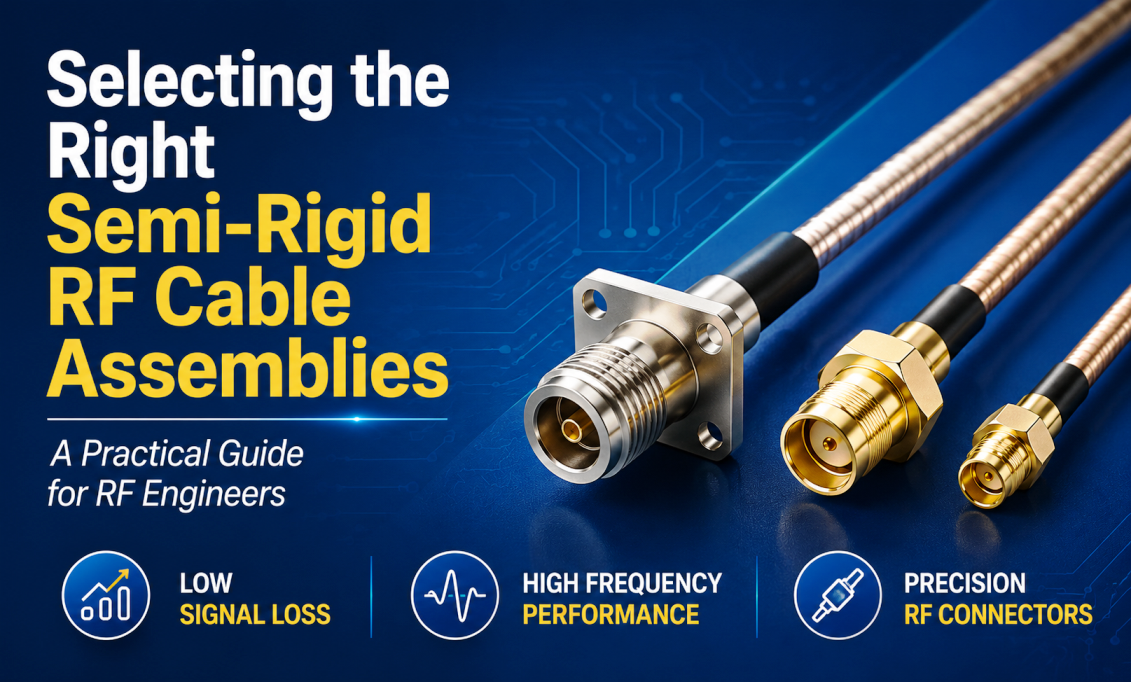
Once you make that choice, everything else follows. The cable becomes electrically better in every measurable way: lower loss, higher shielding effectiveness, tighter impedance control, superior phase stability. It also becomes mechanically different: you can only bend it once. And it becomes expensive: two to five times what a comparable flexible cable costs. Whether that trade makes sense depends entirely on what the cable has to do.
This is the article most brochures should have been. Not a spec sheet with pretty numbers, but a proper look at how semi-rigid cable is built, why it performs the way it does, where it's the right answer, and how to spec one so it delivers what you paid for.
Jump to a section
- What semi-rigid actually is (and what it isn't)
- Anatomy of a semi-rigid cable
- Why a solid outer conductor changes everything
- Common sizes and what each is for
- Semi-rigid vs flexible: a real comparison
- Phase-matched cable pairs
- The trade-offs you're accepting
- Selecting the right semi-rigid cable
- Connectors for semi-rigid
- How semi-rigid assemblies are actually built
- What proper testing looks like
- Failure modes and how they happen
- Questions engineers actually ask
- When semi-rigid is the right answer
What semi-rigid actually is (and what it isn't)
Terminology in this corner of the RF world is genuinely confusing, and half the questions that get asked about semi-rigid are really terminology questions in disguise. Let's clear that up first.
Semi-rigid means the outer conductor is a seamless drawn metal tube (usually copper or tin-plated copper), typically with a solid PTFE dielectric and a solid silver-plated copper center conductor. The cable is formed to shape once, at manufacture, using precision bending tools with dies matched to the cable OD. After forming, the cable holds its shape permanently. You cannot flex it repeatedly without work-hardening the copper and eventually cracking it. Industry designators you'll see include UT-047, UT-085, UT-141, and UT-250 (numbers refer to nominal OD in thousandths of an inch), along with mil-spec equivalents like RG-402 (0.141") and RG-405 (0.086").
Hand-formable or conformable cables (Times Microwave TFlex, Micro-Coax UT-Flex, Belden 82XX series) are a distinct product. They use a corrugated or spirally-wrapped outer conductor that can be bent by hand without tooling. Shielding effectiveness is very good (typically 100 to 115 dB) though not quite semi-rigid class. They cost more than flexible but less than true semi-rigid, and they're what you reach for when you need semi-rigid-like performance in a location where you can't bring a bending fixture.
Semi-flexible is a marketing term that means different things to different manufacturers. Sometimes it means hand-formable. Sometimes it means a very stiff flexible cable. Read the datasheet.
Flexible coax (RG-58, RG-142, RG-400, LMR-series) uses a braided shield and can be bent repeatedly. This is what most of the coaxial cable in the world is. It's fine for the vast majority of applications. It is not what this article is about.
Anatomy of a semi-rigid cable
Four concentric layers, each with real engineering behind the material choice.
Center conductor
Almost always silver-plated copper (SPC) for RF work above 1 GHz. Silver has slightly better conductivity than copper (about 6 percent), which matters because the skin effect drives RF current entirely into the surface layer. Some smaller sizes use silver-plated copper-clad steel (SPCW), where the steel core adds tensile strength and slightly modifies the RF characteristics. Solid conductor, not stranded. In semi-rigid, geometry is everything, and stranded conductors move.
Dielectric
Solid PTFE (Teflon) is the default, and it's chosen for reasons that go beyond the RF story. Low dielectric loss (tan δ around 0.0002 at microwave frequencies), thermal stability from −65 °C to +200 °C, chemical inertness that matters in aerospace fuel bays and medical sterilization cycles, and high dielectric strength (typically 60 to 80 kV/mm). Some cables use low-density PTFE (LDPTFE) or air-spaced PTFE for slightly lower loss and higher velocity of propagation, at the cost of complexity and price.
Outer conductor
A seamless drawn metal tube. This is the defining feature of the entire product category. Options include bare copper (best RF performance, no environmental protection), tin-plated copper (TPC, the workhorse, good solderability and corrosion resistance), aluminum (weight-critical aerospace, requires special connector attachment techniques), and stainless steel (for high-temperature environments up to +250 °C or higher, at the cost of slightly higher loss).
Outer finish
Most semi-rigid ships bare. The metal tube is mechanical protection on its own, and adding a jacket compromises the flush-fit dimensional tolerance the cable was designed around. When jackets are used (usually FEP or PFA on aerospace cable), they're thin, extruded, and carefully specified so they don't change the outer diameter beyond the connector's crimp tolerance.
Why a solid outer conductor changes everything
The reason semi-rigid outperforms flexible cable on almost every electrical spec is worth understanding at first-principles level, because the physics is not that complicated and it explains a lot.
A braided shield, no matter how good, has gaps. Even a 95 percent optical coverage braid, which is excellent, leaves 5 percent of the outer conductor's surface as small holes in the weave. At low frequencies this doesn't matter; the wavelength is huge compared to the gap. At 10 GHz, wavelength in air is 30 mm. At 40 GHz it's 7.5 mm. Individual braid gaps become electrically significant. Some RF leaks out; some external interference leaks in. Signal integrity suffers in ways that don't show up on a DC continuity check.
A seamless drawn tube has no gaps. Zero. The outer conductor is a continuous, unbroken cylinder of metal, and RF current flows smoothly on its inner surface (skin depth in copper at 10 GHz is about 0.66 μm, so the current is confined to a thin surface layer regardless). What you get from this construction:
| Electrical property | Flexible (braid) | Semi-rigid (tube) | Why it improves |
|---|---|---|---|
| Shielding effectiveness | 75 to 100 dB | 120 to 140+ dB | No braid gaps to leak through |
| Insertion loss at 18 GHz | 1.3 to 2.5 dB/m | 0.6 to 1.2 dB/m | Smoother inner surface, less loss |
| VSWR at 18 GHz | 1.3:1 to 1.5:1 | 1.15:1 to 1.25:1 | Uniform geometry means uniform impedance |
| Phase stability vs temp | 100 to 400 ppm/°C | 20 to 100 ppm/°C | Rigid mechanical structure doesn't deform |
| Phase stability vs flex | Poor to moderate | N/A (doesn't flex) | Phase-critical work needs a cable that doesn't move |
The specific numbers vary by exact cable and manufacturer, but the pattern is consistent: semi-rigid is roughly half the loss, two to four times the shielding effectiveness in dB, and dramatically better phase stability compared to the equivalent flexible cable.
Common sizes and what each is for
Semi-rigid cable size is named by outer diameter in thousandths of an inch. The four sizes you'll see most:
| Size (OD) | Common designators | Max frequency | Loss @ 10 GHz | Typical use |
|---|---|---|---|---|
| 0.047" (1.2 mm) | UT-047, UT-034 | 65 GHz | ~2.0 dB/m | Compact modules, PCB-to-connector jumpers, mmWave |
| 0.085" (2.2 mm) | UT-085, RG-405 | 40 GHz | ~1.3 dB/m | Test instruments, aerospace electronics, general microwave |
| 0.141" (3.6 mm) | UT-141, RG-402 | 33 GHz | ~0.8 dB/m | Radar modules, higher power, longer runs |
| 0.250" (6.4 mm) | UT-250 | 18 GHz | ~0.5 dB/m | High-power transmitters, low-loss backbones |
The pattern is straightforward. Larger cable diameter gives you more inner conductor surface area, lower loss, higher power handling, and better tolerance of manufacturing variation. It also gives you a bigger minimum bend radius (a rule of thumb is 3x the OD for a semi-rigid without cracking), heavier weight, and larger connector footprint at the ends. Design starts with "what's my frequency and my power?", moves to "what's my routing space?", and lands on a size.
Semi-rigid vs flexible: a real comparison
The right way to think about this comparison is: what job does the cable have to do?
Reach for semi-rigid when
- The cable path is fixed and known at manufacture
- Phase stability across temperature is critical
- Shielding effectiveness above 120 dB is required
- Space is tight and mechanical rigidity actually helps
- The environment (aerospace, space, high-EMI) demands the best
- Frequencies extend into mmWave (above 20 GHz)
- Long service life without degradation is a hard requirement
Stay with flexible when
- The cable will be moved or reconfigured
- You need field-installable or on-site termination
- Budget is tight and 100 dB shielding is enough
- The routing isn't yet fixed at design time
- Operating frequency is below 6 GHz
- You're building tens of thousands of assemblies for cost-sensitive apps
There's no "better." There's fit-for-purpose. The engineering error most often made here is choosing semi-rigid because it "sounds premium" when a good flexible cable would do the same job for a fifth of the price. The mirror-image error is spec'ing flexible on a phased-array radar module because it "should be cheaper" and then chasing phase mismatch problems for six months.
Semi-Rigid Assemblies Built to Your Drawing
SigmaRF forms UT-047, UT-085, UT-141, and UT-250 semi-rigid to your dimensional specification, with SMA, 2.92 mm, 2.4 mm, 1.85 mm, or SMP/SMPM terminations. Every assembly individually swept for insertion loss and VSWR across the operating band before it ships.
Request a Custom Assembly →Phase-matched cable pairs
This topic almost never appears in general RF cable articles, but it's one of the main reasons semi-rigid exists as a product category. Whenever you have a multi-channel system where the RF signals from different paths have to arrive at the same time (phased-array radar, beamforming, interferometric measurement, MIMO characterization), the electrical length of each cable in the set must match to within a very small tolerance.
"Electrical length" is not the same as physical length. It's how long the RF signal takes to propagate, which depends on the exact velocity of propagation of the dielectric, the exact center-conductor geometry, and the cable's temperature. Two flexible cables of the same nominal length can easily differ by 5 to 10 electrical degrees at 10 GHz. That's enough to ruin an interferometric measurement or degrade a phased-array's beam pattern.
Semi-rigid cables are inherently phase-matchable because the geometry is fixed. When SigmaRF (or any competent supplier) delivers a matched set, each cable in the set is measured on a VNA against a reference, and the physical length is trimmed by the supplier until all cables in the set fall within the specified phase tolerance. Common tolerances:
- ±1 degree at 10 GHz for demanding radar and interferometry
- ±5 degrees at 10 GHz for typical phased-array applications
- ±10 degrees at 10 GHz for MIMO and beamforming characterization
Tighter tolerances cost more because they require more measurement and iteration during manufacture. If you need phase matching, specify the tolerance up front. Adding it after the fact means the assemblies get re-worked, and re-worked semi-rigid is a compromised assembly.
The trade-offs you're accepting
Semi-rigid is not free performance. The construction has real costs, and any engineer specifying semi-rigid should be aware of what they're trading away.
One-time forming
Once formed, the cable cannot be repositioned without work-hardening the outer conductor. Repeated bending will crack it. Every mechanical design constraint has to be finalized before the cable is manufactured. This is why aerospace and defense customers do so much upfront routing simulation.
Cost
Two to five times the cost of comparable flexible cable. The tooling for precision forming is expensive, the connectors are typically precision (SMP, SMPM, 2.92 mm, 2.4 mm) rather than commercial (SMA), and per-assembly VNA testing is standard rather than optional.
Lead time
Custom semi-rigid assemblies are made to order. Standard SMA-to-SMA jumpers in common lengths often ship from stock; anything with specified bends or phase matching runs on order-to-manufacture timelines, typically 3 to 6 weeks in industry.
Vibration coupling
Because semi-rigid transmits mechanical stress directly, vibration at one end couples to the other. In high-vibration environments (rotor-craft, missiles, high-shock test), designers often include short flexible sections at each connector to isolate the assembly from vibration transmitted through the mounting structure.
Selecting the right semi-rigid cable
Six questions get you 90 percent of the way to a proper spec. Answer them before you look at any catalog.
What is the operating frequency range? This drives cable size and connector choice. Above 26.5 GHz you're in 2.92 mm connector territory (or precision 3.5 mm); above 40 GHz means 2.4 mm; above 50 GHz means 1.85 mm. Standard SMA is fine to 18 GHz but not above.
What is the loss budget? Total system insertion loss at the operating frequency. Longer runs need larger diameter cable, and vice versa. If you have 2 dB to spend on the cable at 20 GHz over a 30 cm run, 0.085 semi-rigid gets you there. Try to do the same job on 0.047 and you'll be over budget.
What is the power level? CW and peak. Semi-rigid handles more power than equivalent flexible because the solid outer conductor dissipates heat better. 0.085 is typically rated to 100 W CW at 1 GHz, 30 W at 10 GHz. 0.141 doubles that. 0.250 doubles it again. Peak power ratings are much higher, limited by dielectric strength.
What's the routing? Draw the actual path. Note every bend, its radius, and the distance between bends. Semi-rigid needs at least 3x OD for the bend radius (so 0.141 cable needs 0.42 inches minimum radius on any bend), and it needs a straight section on either side of every bend for the forming tool to grip. This is where a lot of amateur specs come apart: on paper it fits, in reality the forming die can't get to it.
What's the environment? Temperature range, atmosphere (air, vacuum, dry gas), humidity, corrosion exposure, vibration, radiation. Copper outer conductor for most work. Tin-plated copper for improved solderability and mild corrosion resistance. Stainless steel for high-temperature (aerospace engine bays, industrial). Aluminum for weight-critical space applications. PTFE dielectric handles −65 to +200 °C; if you need more, you need a specialty product.
Do you need phase matching? If yes, specify the tolerance and the reference frequency. If no, save yourself the cost.
Connectors for semi-rigid
Semi-rigid connectors attach by soldering the outer conductor tube directly to the connector body. This is where a lot of the price of a proper semi-rigid assembly goes, and where the difference between a good supplier and a bad one shows up.
Precision connectors commonly paired with semi-rigid:
- SMA: workhorse, works to 18 GHz with commercial versions, 26.5 GHz with precision. Solder-attach standard for semi-rigid.
- 3.5 mm: mates with SMA mechanically, precision electrical performance to 26.5 GHz.
- 2.92 mm (K): to 40 GHz, mates with SMA and 3.5 mm.
- 2.4 mm: to 50 GHz, does not mate with SMA (intentionally: prevents accidental damage to precision hardware).
- 1.85 mm (V): to 67 GHz, mates with 2.4 mm.
- SMP: subminiature push-on for board-to-cable interconnect, to 40 GHz.
- SMPM: smaller SMP variant for dense arrays, to 65 GHz.
- N-Type: for larger 0.141 or 0.250 semi-rigid where higher power and lower frequency (to 18 GHz) is the priority.
Which connector to use is driven by frequency, then by mating requirements, then by the mechanical constraints of what board or panel the connector interfaces with. Do not pair a $2 SMA with a $50 semi-rigid cable expecting the SMA won't be the weakest link. It will be.
How semi-rigid assemblies are actually built
A proper semi-rigid manufacturing process is nine to eleven steps, and each one affects the final performance. Skip any of them and the cable is compromised.
1. Precision cut
Cable cut to exact length using a die cutter, not a rotary tool. Rotary cuts distort the tube's roundness and mess with the connector attachment.
2. Strip and prep
Outer conductor and dielectric stripped to precise dimensions matching the connector's mating geometry. The center conductor is exposed to a controlled length. Any error here propagates to VSWR.
3. Deburr and clean
The cut end of the outer conductor is deburred so no rough edge disturbs the electromagnetic field near the connector. The mating surface is cleaned with IPA or an equivalent solvent.
4. Bend to drawing (if formed)
Cable formed to the customer's dimensional drawing using dies matched to the cable OD and bend radius. Each bend inspected against the drawing before proceeding.
5. Connector attachment
Connectors soldered to the outer conductor. Solder joint fillet controlled for uniformity around the circumference. Center pin soldered or fastened to the center conductor per connector spec.
6. Flux removal
All flux residues cleaned from the connector body and mating surfaces. Residues are hygroscopic and become long-term reliability issues.
7. Pin depth verification
Every connector checked with a pin depth gauge to make sure the center pin sits at the correct height. Out-of-spec pin depth causes VSWR problems and can damage mating hardware.
8. Visual inspection under magnification
10x or 20x microscope inspection of every solder joint, every connector face, and every visible portion of the assembly. Defects flagged for rework or reject.
9. Electrical test on VNA
Full S-parameter sweep on a calibrated VNA across the operating band. Insertion loss and VSWR measured. Phase (for phase-matched pairs) verified against tolerance.
10. Documentation
Each assembly gets a serial number, a printed test report, and a certificate of conformance. This is what makes the assembly traceable years later.
11. Packaging
Protective caps on connectors, foam or fixture packaging so the assembly can't move in transit. Shipped with the test data.
What proper testing looks like
A semi-rigid assembly should arrive with test data. The minimum you should expect:
- Insertion loss measured across the specified frequency range on a calibrated VNA, with the trace or the tabulated data included in the test report
- Return loss / VSWR at both ports across the same range
- Phase length when phase-matched pairs are ordered, with the measured phase difference relative to the reference documented at the specified frequency
- Visual pass / fail confirming the assembly passed microscope inspection
- Serial number tying the specific assembly to its test data
- Cable date code and manufacturing traceability information for aerospace and defense use
If your supplier will not provide this documentation, they either don't test every assembly (in which case some fraction of what they ship is out of spec) or they don't want you to know what tolerances they're actually holding. Both are bad signs for anything above commercial-grade cable.
Failure modes and how they happen
Semi-rigid assemblies have long service lives when they're built and installed properly. When they fail, the usual suspects are:
- ✗ Cracks in the outer conductor from someone trying to re-bend the assembly after it was installed. The tube work-hardens and cracks. RF leakage rises, VSWR drifts, the cable is done.
- ✗ Solder joint failure at the connector from mechanical stress. Common when the assembly is under tension at install or when nearby components vibrate against the cable.
- ✗ Over-torqued connectors that damaged the connector's internal geometry. VSWR degrades, sometimes the connector body cracks.
- ✗ Pin depth drift after many mating cycles, especially on SMP and SMPM push-on connectors. Manifests as VSWR degradation.
- ✗ Flux residue corrosion years after installation, if flux was not cleaned properly during manufacture. Shows up as slowly rising insertion loss.
- ✗ Cracks near sharp bends that were formed too tight for the cable size. The bend passes visual inspection but fails under thermal cycling.
- ✗ Moisture ingress at solder joints that were not properly sealed. Aerospace and marine applications are where this bites the most.
Notice how many of these are traceable to manufacture rather than to the cable design itself. This is why choosing a competent supplier matters more than choosing between UT-085 and UT-141.
Questions engineers actually ask
What is a semi-rigid RF cable assembly?
A coaxial cable assembly where the outer conductor is a seamless drawn metal tube (usually copper or tin-plated copper) instead of a braided shield. It is formed to shape once at manufacture using precision bending tools and holds that shape permanently. The seamless outer conductor delivers superior shielding effectiveness (typically 120 to 140 dB), lower insertion loss, better VSWR, and phase stability that a braided cable cannot match. Common in aerospace, radar, satellite, and mmWave test systems.
Can I bend a semi-rigid cable myself?
Not without the right tools. Semi-rigid should be formed on precision bending dies matched to the cable OD, with minimum bend radius typically 3x the OD. Free-hand bending distorts the tube, changes local impedance, and can crack the outer conductor. If you need field-formable cable, use hand-formable or conformable products (like UT-Flex or TFlex), not true semi-rigid.
What is the difference between semi-rigid and hand-formable cable?
Semi-rigid uses a seamless drawn tube for the outer conductor and requires precision tooling to form. Hand-formable (or conformable) uses a corrugated or spirally-wrapped outer conductor that can be shaped by hand without tooling. Hand-formable trades slightly less shielding effectiveness (100 to 115 dB versus 120 to 140+ for semi-rigid) for the practical benefit of field installation without a bending fixture. Cost sits between semi-rigid and flexible.
What size semi-rigid should I use?
Driven by frequency, loss budget, and power. Rough guide: 0.047" (UT-047) for compact mmWave modules to 65 GHz. 0.085" (UT-085 / RG-405) is the workhorse for general microwave to 40 GHz. 0.141" (UT-141 / RG-402) for higher power and slightly lower loss to 33 GHz. 0.250" (UT-250) for high-power transmitter interconnect to 18 GHz. Larger diameter = lower loss and higher power, at the cost of bigger bend radius and heavier weight.
Why is phase stability important?
In multi-channel systems (phased-array radar, interferometry, beamforming, MIMO characterization), signals in different paths must arrive at exact phase relationships. Cable that changes electrical length with temperature or flexure introduces phase drift, which degrades beam patterns, corrupts measurements, and makes calibration nearly impossible. Semi-rigid cables have phase stability of 20 to 100 ppm per degree C, compared to 100 to 400 ppm/°C for typical flexible cable. This is why semi-rigid dominates phase-critical work.
What connectors work with semi-rigid?
Precision connectors soldered directly to the outer conductor. Common choices are SMA (to 18 GHz commercial, 26.5 GHz precision), 3.5 mm (26.5 GHz), 2.92 mm / K (40 GHz), 2.4 mm (50 GHz), 1.85 mm / V (67 GHz), plus SMP and SMPM for board-to-cable interconnect. N-Type is used with larger 0.141 and 0.250 semi-rigid where higher power at lower frequency is the priority. Choice is driven by frequency first, then mating requirements, then mechanical constraints.
How much does a semi-rigid cable assembly cost?
Two to five times a comparable flexible cable assembly. The delta comes from precision tooling for forming, higher-grade connectors, per-assembly VNA test, and lower production volumes. Standard SMA-to-SMA 0.085 jumpers are the cheapest entry point. Formed assemblies with 2.4 mm connectors, phase matching, and mmWave testing sit at the top end. Quotes depend heavily on quantity and specification.
How long do semi-rigid assemblies last?
In a stable environment with no repeated flexure and correct handling of the connectors, service life of 20 to 30 years is realistic. Aerospace and space applications routinely spec them for the full mission life. The connectors usually wear out from mating cycles before the cable itself degrades. High-cycle test assemblies may need replacement after a few thousand connections because of pin wear.
Should I use PTFE or air-spaced dielectric?
Solid PTFE for almost everything: it delivers excellent RF performance, mechanical robustness, and thermal stability. Low-density PTFE or air-spaced dielectric offers slightly lower loss and slightly higher velocity of propagation, at the cost of significantly higher price and reduced mechanical margin. Use air-spaced when you need every last tenth of a dB (broadcast, satellite, precision measurement) and can accept the mechanical trade.
When semi-rigid is the right answer
Semi-rigid is not for every RF system. It is for the systems where the RF interconnect has to be as close to invisible as physically possible: no measurable phase drift over the operating temperature range, no shielding leakage that shows up as receiver noise, no impedance perturbation that pushes VSWR beyond spec. When those requirements are real (radar, satellite, mmWave test, aerospace, precision measurement), the seamless outer conductor is not a nice-to-have. It is the reason the system works.
And when those requirements are not real, semi-rigid is expensive theater. There is no engineering virtue in overspec'ing a jumper cable that just needs to carry a 900 MHz signal from a radio to an antenna two feet away. Use the right cable for the job.
The judgment lives in that assessment. Understand what semi-rigid actually does, know how it's built, spec the trade-offs honestly, choose a supplier who tests every assembly and ships the data, and it becomes the boring, reliable part of your system. Which, at these frequencies, is a rare and valuable thing.
Precision Semi-Rigid Assemblies from SigmaRF
UT-047, UT-085, UT-141, and UT-250 semi-rigid formed to drawing, with SMA, 3.5 mm, 2.92 mm, 2.4 mm, 1.85 mm, SMP, SMPM, or N-Type terminations. Phase-matched pairs available. Every assembly individually VNA-swept, with test data shipped alongside. Built for aerospace, radar, satellite, mmWave test, and any application where the RF interconnect has to disappear into the signal path.
Standard Assemblies Custom Assemblies Talk to an Engineer- Why Cheap RF Cable Assemblies Fail: Construction Shortcuts and How to Spot Them
- Solving Antenna Range Loss on an IoT Device: A Worked Diagnostic Example
- SMA Mating Cycles: How Many Connections Can an SMA Survive?
- RG58 Attenuation: Datasheet Specs vs Real-World Loss
- VNA Testing for Cable Assemblies: How VSWR and Insertion Loss Verification Works
- How a Custom Coaxial Cable Assembly Is Built, Step by Step
- Cellular Repeater and DAS Cable Selection: In-Building Coverage Guide
- Wi-Fi HaLow (802.11ah): Sub-GHz Wi-Fi and Its Antenna/Cable Needs
- RF Interconnects for Test Labs: Building a Reliable VNA Bench
- Direct-to-Cell Satellite and IoT: What It Means for Ground Hardware