Wi-Fi Module Connection to Antenna: RF Connection Guide for Engineers
Published on 7/29/2026 • Updated on 8/1/2026
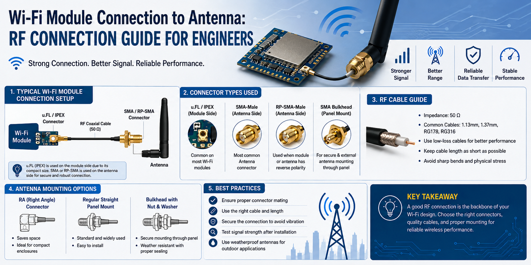
Almost always, the answer is somewhere in the RF path between the module and the antenna. A U.FL that was hand-mated one too many times. A pigtail that got kinked during enclosure assembly. A bulkhead SMA torqued by hand and now sitting at 1.6 dB of insertion loss because the center pin wasn't quite seated. A "compatible" antenna that turns out to be 75 ohms because someone in purchasing got a good deal. Wi-Fi modules generate very modest RF power (10 to 23 dBm typically), and every dB you lose between the module and the antenna is a dB off both your range and your receive sensitivity.
This guide walks through the whole path: board-level connectors, pigtail cable, panel-mount connectors, external antenna interfaces. What each option is, when to use it, and the mistakes that quietly cost you dB. Aimed at hardware engineers and product designers who need Wi-Fi to work reliably in production, not at RF specialists who already know all this.
On This Page
- Why Every dB Counts in a Wi-Fi Link
- Wi-Fi Frequency Bands and What Changes at Each
- The Typical Signal Path
- Board-Level Connectors: U.FL, MHF, and the Terminology Mess
- Board Connector Comparison
- Coaxial Cable Options and Loss at Wi-Fi Frequencies
- Panel-Mount Connector Styles
- Straight vs Right-Angle
- External Connectors and the RP-SMA Gotcha
- MIMO Matched Pigtails
- Worked Example: Wi-Fi 6E IoT Gateway
- Selection Matrix by Application
- Common Mistakes and How to Avoid Them
- Frequently Asked Questions
- Bottom Line
Why Every dB Counts in a Wi-Fi Link
A typical Wi-Fi module transmits at 15 to 20 dBm at the chip output. Regulatory limits (FCC Part 15 in the US, CE in Europe, TELEC in Japan) cap the effective radiated power for consumer Wi-Fi at around 30 dBm EIRP, and most designs run well below that. Which means the antenna is expected to add the difference in gain (typically 2 to 5 dBi for a small dipole, up to 8 dBi for a well-designed sector), and the interconnect is expected to add nothing.
Every dB of unnecessary loss in the pigtail chain takes away from both directions at once:
| Interconnect Loss | Power at Antenna | Approx Range Impact | Real-World Result |
|---|---|---|---|
| 0.5 dB | 89% | ~3% shorter | Well-designed pigtail |
| 1.0 dB | 79% | ~6% shorter | Acceptable for most products |
| 2.0 dB | 63% | ~12% shorter | Noticeable range loss |
| 3.0 dB | 50% | ~17% shorter | Field complaints about dead spots |
| 6.0 dB | 25% | ~30% shorter | Product is functionally broken |
The range impact numbers are approximate (free-space is 6 dB per doubling of distance, but real environments are more like 8 to 10 dB per doubling because of obstructions), but the direction is right. Small savings in interconnect loss compound with everything else in the RF budget.
Wi-Fi Frequency Bands and What Changes at Each
Wi-Fi has grown into a multi-band system, and the interconnect requirements are different at each band. A cable and connector combination that's fine at 2.4 GHz can be marginal at 6 GHz. Know what band you're actually targeting before you spec the pigtail.
| Band | Standards | Loss @ 100 mm 1.13 mm micro-coax | Interconnect Notes |
|---|---|---|---|
| 2.4 GHz | Wi-Fi 4, 5, 6, 7 | ~0.20 dB | Forgiving band, most cables and connectors work fine |
| 5 GHz | Wi-Fi 5, 6, 6E, 7 | ~0.30 dB | Modest step-up, still forgiving for short runs |
| 6 GHz | Wi-Fi 6E, 7 | ~0.35 dB | Micro-coax fine, but every dB matters more |
Two things to notice. First, loss rises with frequency, but not dramatically over the Wi-Fi range: 100 mm of good micro-coax adds well under half a dB even at 6 GHz. Second, connector loss becomes proportionally more important on short pigtails. On a 100 mm assembly at 6 GHz, one U.FL connector at 0.3 dB is the same as the entire cable. On a 300 mm assembly, it's a third.
The Typical Signal Path
Almost every embedded Wi-Fi product follows the same six-stage path from module to antenna, and each interface is a place where things go wrong.
↓
2. Board-Level Connector (U.FL / MHF4 / MMCX)
↓
3. Coaxial Pigtail (micro-coax, RG178, or RG316)
↓
4. Panel-Mount Connector (bulkhead SMA / RP-SMA / N-Type)
↓
5. External Antenna Interface (mates with the panel-mount)
↓
6. Antenna (radiates into free space)
Every impedance on this path is 50 ohms. Not 75, not 300, not anything else. If any component in the chain is off-impedance, you get reflections, VSWR climbs, and effective power drops. This is why using a "TV coax" fitting (75 ohm F-Type) in a Wi-Fi system is not a shortcut. It is a mistake.
Board-Level Connectors: U.FL, MHF, and the Terminology Mess
If you have ever tried to buy a "U.FL to SMA" cable and gotten something that doesn't fit your module, you have run into the terminology mess. Let's untangle it.
U.FL is Hirose's trade name for their ultra-miniature coaxial connector. Hirose spec sheets call it the U.FL series. Nobody outside Hirose uses that name consistently.
MHF (Micro Hirose Family) is I-PEX's competing product line. Because the two families were designed to be mechanically and electrically compatible, they mate with each other. This is why "U.FL to SMA" cables sold on general distribution often work with MHF connectors, and vice versa.
Where it gets messy is the sub-variants. There are several sizes in the I-PEX MHF family, each smaller than the last:
| Name | Mates With | Max Frequency | Typical Use |
|---|---|---|---|
| U.FL / MHF I | U.FL, MHF I | 6 GHz | ESP32, Wi-Fi 4/5/6, general embedded |
| MHF II (W.FL) | MHF II only | 6 GHz | Older M.2 modules, some LTE |
| MHF III | MHF III only | 15 GHz | Less common, some 5G modules |
| MHF 4 (MHF 4L) | MHF 4 only | 15 GHz | Modern M.2 Wi-Fi 6E/7 cards, LTE, 5G |
| MHF 5 (MHF 5L) | MHF 5 only | 20 GHz | Newest and smallest, mmWave-adjacent uses |
The important rule: MHF II, III, 4, and 5 are all different mechanical sizes and do not mate with each other. Only U.FL and MHF I are cross-mating. If your Wi-Fi card has MHF 4 connectors and you buy "U.FL to SMA" pigtails, they will not fit. Check the module datasheet for the exact connector type before ordering.
Board Connector Comparison
| Connector | Height | Mating Cycles | Loss @ 6 GHz | Notes |
|---|---|---|---|---|
| U.FL / MHF I | ~2.5 mm | ~30 | ~0.3 dB | Universal on ESP32 and small modules |
| MHF 4 | ~1.2 mm | ~30 | ~0.25 dB | Modern M.2 standard |
| MMCX | ~4.0 mm | 500+ | ~0.2 dB | Snap-on, robust, for repeated mating |
| SMA (edge) | ~9.0 mm | 500+ | ~0.15 dB | Bigger, more robust, PCB edge-mount option |
If the board connector is going to see repeated mating (user-serviceable antenna, test connection, dev kit), don't use U.FL or MHF. Use MMCX at minimum, ideally SMA. The mating-cycle life is 15x better and the mechanical integrity survives being unplugged in the field.
Coaxial Cable Options and Loss at Wi-Fi Frequencies
The pigtail is the biggest single loss contributor once you get above about 100 mm of length. Choose the cable to match the length and the frequency, not just what's cheap.
| Cable | OD | Loss @ 2.4 GHz | Loss @ 5 GHz | Loss @ 6 GHz | Best For |
|---|---|---|---|---|---|
| 1.13 mm micro-coax | 1.13 mm | ~2.0 dB/m | ~3.0 dB/m | ~3.5 dB/m | Internal pigtails under 200 mm |
| 1.32 mm micro-coax | 1.32 mm | ~1.7 dB/m | ~2.5 dB/m | ~3.0 dB/m | Slightly better performance internal |
| RG178 | 1.8 mm | ~1.5 dB/m | ~2.3 dB/m | ~2.6 dB/m | General-purpose, moderate flexibility |
| RG316 | 2.5 mm | ~0.95 dB/m | ~1.4 dB/m | ~1.6 dB/m | Longer internal runs, industrial |
| LMR-100A | 2.8 mm | ~0.80 dB/m | ~1.2 dB/m | ~1.4 dB/m | Low-loss when the run is longer |
| LMR-195 | 4.9 mm | ~0.45 dB/m | ~0.75 dB/m | ~0.85 dB/m | External runs, outdoor, longer than 500 mm |
A rough rule: use 1.13 mm or 1.32 mm micro-coax for internal pigtails under 200 mm at any Wi-Fi band. Above 200 mm, step up to RG316 or LMR-100A. Above 500 mm, use LMR-195 or better. The step-up is not just about loss; larger cables also have better shielding, which matters when the pigtail runs past switching supplies or motor drivers.
Custom Wi-Fi Pigtails Built to Spec
U.FL, MHF I, MHF 4, MMCX, and SMA/RP-SMA panel-mount configurations, in 1.13/1.32 micro-coax, RG178, RG316, or LMR series. Any length, straight or right-angle, matched pairs for MIMO if you need them. Assemblies individually swept for VSWR before shipment.
Request a Custom Pigtail →Panel-Mount Connector Styles
Where the pigtail exits the enclosure, you need a connector that both makes the RF connection and physically holds the antenna in place against whatever the environment throws at it. Three main styles:
Bulkhead
Threaded connector body passes through a single hole in the panel, held in place by a nut on the inside. Simplest, smallest footprint, cheapest.
Use for: IoT gateways, Wi-Fi routers, test equipment, most indoor devices.
2-hole flange
Connector body with a flange containing two screw holes. Better mechanical support than bulkhead, resists cable tug and moderate vibration.
Use for: industrial controllers, medical devices, transportation, indoor equipment with heavy antennas.
4-hole flange
Square flange with four mounting holes. Highest mechanical robustness. Standard on aerospace, defense, railway, marine, and heavy-duty industrial.
Use for: outdoor gateways, mobile equipment, high-vibration environments, anywhere reliability matters more than cost.
The single most common panel-mount mistake is using a bulkhead where a flange was needed. On a bulkhead, everything holding the connector in place is one nut and the panel material around one hole. Repeated pull on the antenna cable eventually rotates the connector or cracks the panel. Flanges spread the load across two or four fasteners, and the connector body itself takes the strain instead of the panel.
Straight vs Right-Angle
Straight connectors route the pigtail directly out the back. Right-angle connectors bend the cable 90 degrees just past the connector. The choice is usually driven by enclosure geometry more than electrical performance.
Right-angle connectors add roughly 0.05 to 0.1 dB more loss than straight ones at Wi-Fi frequencies. That's electrically negligible. What matters more is that they avoid the situation where a straight connector forces a tight cable bend against the inside of the panel, which is much worse for the cable than a right-angle at the connector.
Rule of thumb: if you have less than about 20 mm of internal depth behind the panel, use a right-angle. If you have room for the pigtail to make a gentle bend, straight is fine.
External Connectors and the RP-SMA Gotcha
The external side of the panel-mount connector is what the antenna plugs into. Common choices:
| Connector | Max Frequency | Where You Find It |
|---|---|---|
| RP-SMA | 18 GHz | Wi-Fi routers, most consumer Wi-Fi antennas |
| SMA | 18 GHz | Industrial equipment, test gear, IoT |
| N-Type | 11 GHz | Outdoor Wi-Fi, industrial antennas, higher power |
| TNC | 11 GHz | Mobile, transportation (vibration-resistant thread) |
| BNC | 4 GHz | Legacy equipment, low-frequency only (not Wi-Fi 5+) |
MIMO Matched Pigtails
Wi-Fi 5 (802.11ac) introduced 2x2 MIMO as the mainstream configuration. Wi-Fi 6, 6E, and 7 use 2x2, 4x4, and increasingly 8x8. Every MIMO stream is a separate RF chain: separate transmit, separate receive, separate pigtail, separate antenna. Which introduces a consideration the source article doesn't cover: the pigtails should match.
If one pigtail has 1.0 dB of loss and the other has 1.5 dB, your MIMO algorithms are seeing an imbalanced channel and cannot fully exploit spatial multiplexing. Modern chipsets compensate to a point, but there's a range where the difference is small enough to correct and a range beyond which it isn't. Typical tolerance for good MIMO performance is under 0.5 dB channel-to-channel loss variation.
For products above Wi-Fi 5, order pigtails as matched pairs (or matched quads for 4x4). The supplier measures each cable on a VNA and selects sets that fall within specification. This is worth doing at the pigtail level rather than trying to correct in software.
Worked Example: Wi-Fi 6E IoT Gateway
A Wi-Fi 6E industrial gateway with a module putting out 20 dBm at 6 GHz. The antenna is an external 5 dBi dipole mounted on a 4-hole flange RP-SMA. Internal pigtail runs 150 mm from the module's MHF 4 port to the panel-mount. Let's walk the RF budget.
Case A: Well-designed pigtail
1.32 mm micro-coax, 150 mm, MHF 4 to RP-SMA bulkhead panel-mount.
MHF 4 connector loss: −0.25 dB
Cable loss (0.15 m × 3.0 dB/m): −0.45 dB
RP-SMA connector loss: −0.20 dB
Total path loss: −0.90 dB
Power at antenna: +19.1 dBm
Antenna gain: +5.0 dBi
EIRP: +24.1 dBm
Case B: Under-spec'd pigtail
Same 150 mm, but cheap 1.13 mm micro-coax that's been re-mated at U.FL five times, plus a hand-tightened RP-SMA at the panel.
Worn MHF 4: −0.6 dB (worse after re-mates)
Cable loss (0.15 m × 3.5 dB/m): −0.55 dB
Under-torqued RP-SMA: −0.8 dB (and VSWR climbs)
Total path loss: −1.95 dB
Power at antenna: +18.05 dBm
Antenna gain: +5.0 dBi
EIRP: +23.05 dBm
The delta between Case A and Case B is about 1 dB of EIRP. That's roughly a 6 percent range reduction. Multiply that by the receive path (which also loses 1 dB), and you're looking at 12 to 15 percent less coverage in each direction. On a gateway trying to hit sensors at the far end of a warehouse, that's the difference between reliable connections and intermittent ones.
Selection Matrix by Application
| Application | Board Connector | Cable | Panel-Mount |
|---|---|---|---|
| Consumer Wi-Fi router | Internal only | 1.13 mm micro | RP-SMA bulkhead |
| ESP32-based IoT sensor | U.FL | 1.13 mm micro | RP-SMA or SMA bulkhead |
| Industrial controller | U.FL or MMCX | RG316 | SMA 2-hole flange |
| Outdoor gateway | MHF 4 or SMA | RG316 or LMR-100A | N-Type 4-hole flange |
| Medical device | MMCX or SMA | RG316 | SMA 2-hole flange |
| Drone / UAV | MHF 4 | 1.13 mm micro | SMA bulkhead (weight) |
| Robot / AGV | U.FL to MMCX | RG316 | Right-angle SMA panel |
| Railway / marine | SMA | RG316 or LMR-195 | TNC 4-hole flange |
| Test / lab instrument | SMA | RG316 or precision | SMA precision bulkhead |
Common Mistakes and How to Avoid Them
- ✗ Ordering "U.FL cables" when the module actually has MHF 4. Check the module datasheet before you order pigtails.
- ✗ Designing a U.FL as a user-serviceable connection. It's rated for 30 mates. Users will exceed that on day one.
- ✗ Mating SMA to RP-SMA and forcing it. They will not fit, and forcing damages both connectors.
- ✗ Using 75 ohm TV coax "because it's cheaper." VSWR wrecks the link.
- ✗ Running the pigtail past a switching supply or DC motor without regard for EMI coupling.
- ✗ Kinking micro-coax during enclosure assembly. Micro-coax has a small bend radius, but "small" is not "zero."
- ✗ Hand-tightening the bulkhead SMA. Under-torque leaks RF and drifts under vibration. Use a calibrated wrench.
- ✗ Ordering unmatched pigtails for MIMO products. The loss imbalance costs you MIMO gain.
- ✗ Using a bulkhead where the antenna is heavy or subject to vibration. Move to a flange.
- ✗ Skipping the pigtail on the FCC / CE test setup and then adding it in production. The certification is invalid if the RF path changed.
Frequently Asked Questions
What is a U.FL connector and where is it used?
U.FL is Hirose's ultra-miniature coaxial connector, roughly 2.5 mm tall, used to connect an internal RF cable to a Wi-Fi or Bluetooth module. It appears on almost every ESP32 module, Raspberry Pi wireless card, and small IoT module in the industry. Compatible with I-PEX MHF I connectors. Rated for about 30 mating cycles, so use it for permanent internal connections, not for user-serviceable interfaces.
What is the difference between U.FL and MHF 4?
Both are ultra-miniature RF connectors, but they are physically different sizes. U.FL (and its I-PEX equivalent MHF I) is about 2.5 mm tall. MHF 4 is smaller at about 1.2 mm tall and does not mate with U.FL. Modern M.2 Wi-Fi 6E and 7 cards typically use MHF 4. Older embedded modules typically use U.FL. Check the module datasheet before ordering pigtails.
What is the difference between SMA and RP-SMA?
Electrically identical, mechanically reversed. RP-SMA (Reverse Polarity SMA) swaps the male and female pin/socket genders while keeping the thread the same. A standard SMA male has a center pin; an RP-SMA male has a center socket. Wi-Fi routers and most consumer Wi-Fi antennas use RP-SMA. Industrial and test equipment use standard SMA. They do not mate correctly with each other and forcing them damages both connectors.
Should I use bulkhead or flange-mount for my Wi-Fi antenna?
Bulkhead is fine for lightweight antennas in low-vibration environments (Wi-Fi routers, IoT sensors, indoor test equipment). Use a 2-hole flange for industrial controllers, medical devices, and any product where the antenna experiences mechanical stress. Use a 4-hole flange for outdoor, transportation, marine, aerospace, and heavy-antenna applications. When in doubt, go one step heavier; a flange never causes problems, but an inadequate bulkhead does.
How long can my Wi-Fi pigtail be?
Keep it as short as physically possible. For 1.13 mm micro-coax, stay under 200 mm for reasonable loss at 6 GHz. For 300 mm to 500 mm runs, step up to RG316 or LMR-100A. Above 500 mm, use LMR-195 or better. Every extra centimeter costs you signal at both ends of the link.
Does cable loss really matter at Wi-Fi frequencies?
Yes. Wi-Fi modules only put out 15 to 23 dBm to begin with, so every dB matters proportionally more than it does on a 43 dBm cellular RRU. On a marginal link, 1 dB of extra loss can be the difference between reliable coverage and intermittent drops. And receive path losses reduce sensitivity, which directly cuts your range regardless of your transmitter.
Why do MIMO Wi-Fi products need matched pigtails?
Wi-Fi 5, 6, 6E, and 7 use multiple parallel RF chains (2x2, 4x4, 8x8) to achieve high throughput via spatial multiplexing. If one pigtail has significantly more loss than another, the MIMO algorithms see an unbalanced channel and cannot fully exploit the spatial diversity. Target under 0.5 dB variation across the pigtails in a set. This is normally achieved by ordering matched pairs (or quads) from the supplier who selects them after VNA measurement.
Can I use TV coax (RG6) for Wi-Fi?
No. RG6 is 75 ohm, designed for television and satellite. Wi-Fi is 50 ohm. Using 75 ohm cable in a 50 ohm system causes reflections, high VSWR, and significant power loss. It might sort of work at 2.4 GHz over very short lengths, but the link is compromised and you'll never meet regulatory or performance specs.
Does adding a right-angle connector reduce Wi-Fi performance?
Very slightly. A right-angle connector typically adds 0.05 to 0.1 dB more insertion loss than a straight one at Wi-Fi frequencies. That's electrically negligible. In practice, right-angle connectors often improve overall performance because they eliminate tight cable bends that would otherwise be needed to route a straight connector, and tight cable bends cost you more than the connector geometry does.
Bottom Line
The RF path between your Wi-Fi module and antenna is not filler. Every component in that chain (board connector, pigtail, panel-mount, external connector) contributes to your final product's range, reliability, and regulatory compliance. Get the choices right and the interconnect disappears from your problem list. Get them wrong and it becomes the reason your product underperforms in ways that are hard to diagnose after the fact.
Practical rules: check the module datasheet before ordering pigtails to know whether you need U.FL, MHF 4, or something else. Don't design U.FL as a user-serviceable connection. Use the smallest cable that meets your loss budget, stepping up to RG316 or LMR-100A when the run is over 200 mm. Choose a flange-mount connector for anything that will see mechanical stress. Match your MIMO pigtails. Torque every threaded connector with a calibrated wrench. And do not mix SMA and RP-SMA, ever.
Do those things and Wi-Fi 6E and 7 designs work as intended. Skip them and you spend three months in field returns learning what went wrong.
Wi-Fi Pigtails and Panel-Mount Assemblies from SigmaRF
U.FL, MHF I, MHF 4, MMCX, and SMA board-side connectors. 1.13 mm and 1.32 mm micro-coax, RG178, RG316, and LMR-series cable. SMA, RP-SMA, N-Type, and TNC panel-mount in bulkhead, 2-hole flange, and 4-hole flange, straight or right-angle. Matched pairs for MIMO. Every assembly individually swept for VSWR and insertion loss before it ships.
Standard Assemblies Custom Assemblies Talk to an Engineer- Why Cheap RF Cable Assemblies Fail: Construction Shortcuts and How to Spot Them
- Solving Antenna Range Loss on an IoT Device: A Worked Diagnostic Example
- SMA Mating Cycles: How Many Connections Can an SMA Survive?
- RG58 Attenuation: Datasheet Specs vs Real-World Loss
- VNA Testing for Cable Assemblies: How VSWR and Insertion Loss Verification Works
- How a Custom Coaxial Cable Assembly Is Built, Step by Step
- Cellular Repeater and DAS Cable Selection: In-Building Coverage Guide
- Wi-Fi HaLow (802.11ah): Sub-GHz Wi-Fi and Its Antenna/Cable Needs
- RF Interconnects for Test Labs: Building a Reliable VNA Bench
- Direct-to-Cell Satellite and IoT: What It Means for Ground Hardware