RF Coaxial Cable & Cable Assembly FAQ: 40+ Questions Engineers and Buyers Ask, Answered
Published on 9/16/2026 • Updated on 9/16/2026
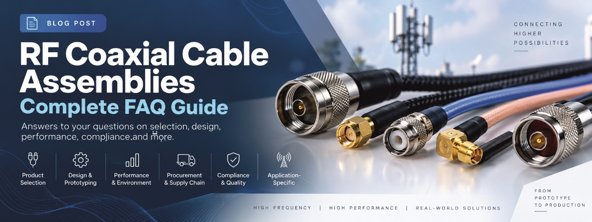
It is organized the way a project actually unfolds: selecting the cable and connectors, deciding between standard and custom, specifying prototypes, handling environmental requirements, managing procurement and volume, meeting compliance, and matching assemblies to specific applications. At the end you'll find a 10-step specification sequence and a worked example spec you can copy for your next RFQ.
Where a question deserves a full article of its own, we've written one; this page cross-references our detailed guides on cable selection, VSWR, assembly design, semi-rigid cable, and coax versus waveguide where relevant.
On This Page
Product Selection and Specifications
What is the difference between an RF coaxial cable and an RF cable assembly?
An RF coaxial cable is the cable itself: center conductor, dielectric, shield, and jacket, built to carry RF signals at a controlled impedance. An RF cable assembly is that cable cut to length and terminated with connectors (SMA, N-Type, TNC, BNC, 2.92 mm, and so on), making it a complete interconnect ready to install. RG316 is a cable; an RG316 with SMA males at both ends, built to a specified length and tested, is a cable assembly.
50 ohm vs 75 ohm coaxial cable: which should I use?
Match the system, not the cable spec sheet. 50 ohm is the standard for RF communications, wireless infrastructure, antennas, cellular, radar, test equipment, and general RF electronics. 75 ohm is the standard for video, broadcast, CATV, and satellite distribution. Never choose between them on attenuation alone: the entire chain (transmitter, PCB, connectors, cable, antenna) should hold one impedance, because a mismatch anywhere reflects power everywhere.
How do I choose the right RF coaxial cable type?
Select on parameters, not on cable name: frequency range, length, allowable attenuation, impedance, power level, VSWR requirement, bend radius, flexing, temperature, indoor or outdoor, mechanical environment, connector compatibility, weight and diameter, phase stability, and any regulatory requirement. As rough anchors: RG316 for compact flexible assemblies, RG58 for general-purpose 50 ohm work, LMR-400-class for lower loss on longer runs, semi-rigid or microwave-grade cable when frequency, shielding, or phase stability get demanding. Then confirm against the actual manufacturer datasheet, because two cables sharing a generic designation can differ meaningfully. Our full coaxial cable selection guide walks this decision step by step.
What is the best RF cable for high frequencies such as 18 GHz, 40 GHz, or mmWave?
There is no single best cable; there are frequency tiers. Approaching 18 GHz, specialized flexible microwave cables with quality SMA or 3.5 mm connectors serve well. At 26.5 GHz, 40 GHz, and beyond, the connector system drives the design: 2.92 mm (K) to about 40 GHz, 2.4 mm and 1.85 mm (V) above that. SigmaRF builds precision assemblies to 40 GHz through its USA capability. The critical habit for mmWave: specify the frequency rating of the complete finished assembly, not the cable's nominal rating, because the assembly is only as fast as its slowest element.
How do I calculate insertion loss for a coaxial cable assembly?
Cable loss = attenuation per unit length × length, at your operating frequency. Example: 0.25 dB/m × 4 m = 1.0 dB. Then add connector and transition losses, typically 0.1 to 0.2 dB per quality connector, for the total: assembly loss ≈ cable loss + connector losses. For precision work, use the measured insertion loss of the finished assembly (which is why SigmaRF sweeps every assembly on a VNA) rather than a calculation from the cable datasheet alone.
What connectors are best for RF cable assemblies?
Select by frequency, power, mechanical duty, mating interface, and environment. The common families and where they fit:
| Connector | Typical Applications |
|---|---|
| SMA | RF modules, wireless, instrumentation, antennas |
| N-Type | Outdoor wireless, antennas, cellular, higher power |
| TNC | Rugged, vibration-exposed RF and communications |
| BNC | Test equipment, instrumentation, lower-frequency RF |
| 3.5 mm | Microwave, test and measurement |
| 2.92 mm (K) | Microwave to approximately 40 GHz |
| 2.4 mm | Higher-frequency microwave |
| 1.85 mm (V) | Millimeter-wave and high-frequency test |
One caution: frequency capability depends on the exact connector design, interface, and cable pairing. Not every SMA performs the same, and a connector rated to 18 GHz on one cable may not achieve it on another.
Straight vs right-angle RF connectors: when should I use each?
Straight when space allows the cable to exit directly; right-angle when the enclosure is tight, the cable must turn immediately at the connector, or PCB edge clearance is restricted. A right-angle connector saves routing space but has slightly different insertion loss, VSWR, and mechanical characteristics than its straight sibling, so let the actual mechanical envelope of the equipment decide, and specify the choice explicitly on the drawing.
What is the minimum bend radius for RF coaxial cables?
It depends entirely on the specific cable construction. Flexible miniature cables tolerate tight bends; large low-loss cables need generous radii; semi-rigid, conformable, and corrugated cables each have their own forming limits. Do not rely on generic rules of thumb unless the manufacturer's datasheet permits them; the datasheet's stated minimum bend radius is the specification. Exceeding it distorts the internal geometry, which shows up as increased VSWR, higher attenuation, phase shifts, or outright mechanical damage.
Flexible vs semi-rigid vs corrugated RF cables: pros and cons?
Flexible cable is easiest to route and right for anything involving movement or repeated handling. Semi-rigid holds a formed geometry permanently, delivering the best shielding and the most predictable RF performance for microwave equipment, instrumentation, and aerospace, at the price of one-time forming rather than flexing (see our complete semi-rigid guide for the details). Corrugated cable serves large outdoor transmission systems: low attenuation over long distances with more installation flexibility than rigid line. Choose on how the cable will actually be installed and used, not on electrical performance alone.
When are phase-matched RF cable assemblies needed?
Whenever multiple signal paths must hold a controlled phase relationship: antenna arrays, beamforming, phased-array radar, direction finding, MIMO, multi-channel test systems, and synchronized clock distribution. Matching can be specified as maximum phase difference, electrical-length difference, or time-delay difference. Critically, define the frequency range and the temperature range over which the match must hold, because cable phase shifts with both, and a set matched at one bench temperature is not automatically matched across an operating range.
What is the power handling capacity of RF coaxial cables?
Not a fixed number on the label. Power capacity depends on frequency (capacity falls as frequency rises), cable diameter and dielectric, connector design, VSWR (a bad match creates voltage and current maxima that derate the cable further), ambient temperature, heat dissipation, duty cycle, and altitude. Always work from the manufacturer's power-rating curve for the exact assembly at the actual operating condition, and derate for VSWR and temperature per that curve.
What VSWR and return loss should I require for an RF cable assembly?
VSWR measures impedance match (lower is better); return loss expresses the same thing as reflected power in dB (higher is better). As anchors: 1.2:1 is a very good match, 1.5:1 is acceptable for many general applications, and demanding microwave and test work requires tighter numbers. The requirement should come from your system specification at your operating frequency, not from an arbitrary round number: over-specifying VSWR raises cost for nothing, under-specifying it costs you power and measurement accuracy. Our VSWR and impedance matching guide covers the conversions and the physics.
Standard vs Custom Assemblies
Standard vs custom RF cable assemblies: which is better?
Neither, universally. Standard assemblies win when the cable, connectors, length, and performance you need already exist as a catalog product: simpler procurement, less engineering effort, faster delivery. Custom wins when you need a specific length, an uncommon connector pair, a particular bend orientation, phase matching, special jacketing, defined testing, or an environmental spec the catalog doesn't carry. Most production programs use both.
When should I choose custom over off-the-shelf?
The clear triggers: non-standard length, different connectors at each end, right-angle or bulkhead requirements, a mandated cable type, a controlled bend radius, engineered strain relief, unusual environmental exposure, phase matching, low-PIM performance, or labeling and traceability requirements. For production equipment there's a quieter benefit: a custom assembly delivered in the exact required configuration cuts installation time on every unit built, which often pays for the customization by itself.
Can I get custom-length assemblies with specific connectors?
Yes, routinely. A complete request looks like: low-loss 50 ohm coax, 850 mm, End A SMA male straight, End B SMA female bulkhead, DC to 6 GHz, VSWR ≤ 1.30:1, UV-resistant jacket, 50 pieces. One detail that prevents disputes later: state how the length is measured (connector-to-connector, cable cut length, or another datum), because a 10 mm ambiguity on a tight enclosure is a real problem.
What should a custom RF cable assembly specification include?
Sixteen items cover it: electrical performance, cable construction, connector type and gender, connector orientation, assembly length, bend requirements, strain relief, environmental conditions, shielding, VSWR or return loss, insertion loss, power handling, phase requirements, labeling, testing, and applicable standards. The principle: the more precisely these are defined, the less room for interpretation during manufacturing, and interpretation is where surprises come from.
Build-to-print vs fully custom: what's the difference?
Build-to-print: you provide the finished drawing or approved part definition, and the manufacturer builds exactly that. Right when the design is already validated. Fully custom: you provide the application requirements, and the supplier's engineers help select the cable, connectors, termination, mechanical configuration, and test plan. Right when you know what the assembly must do but haven't finalized how. SigmaRF supports both paths, and many projects start fully custom and graduate to build-to-print once the first article is approved.
Prototyping and Design
What information do I need to provide for a custom assembly quote?
Minimum: cable type or required performance, impedance, length, connector at each end with gender, straight or right-angle, frequency range, quantity, and required delivery date. To sharpen the quote: insertion loss and VSWR limits, power level, temperature range, indoor or outdoor, bend radius, flex life, phase matching, low-PIM, shielding, jacket material, test and certification requirements, and a drawing or sample if one exists. Send what you have; a capable supplier fills gaps with questions, not assumptions.
How should I specify RF cable assemblies for prototypes?
Specify the application, not just a part name. Instead of "RG58 with SMA," write: 50 ohm assembly, 1.5 m, SMA male straight both ends, 0 to 6 GHz, low-loss cable, VSWR ≤ 1.30:1, insertion loss to be measured, black UV-resistant jacket, 10 pieces. The difference: the first version locks in a cable that may be wrong for the job; the second gives the manufacturer what it needs to recommend the right construction, which is exactly what the prototype phase is for.
What are RF cable assembly design best practices?
Keep the cable as short as practical; every meter is loss. Avoid adapters; every interface is a discontinuity and a failure point. Hold the manufacturer's minimum bend radius, and keep bends away from the connector interfaces. Match connector and cable as a qualified pair. Never let the cable mechanically load a connector or its solder joints; strain-relieve instead. And as frequency rises, workmanship dominates: at microwave, a slightly imperfect termination that would be invisible at 400 MHz becomes a visible VSWR spike. Our RF cable assembly design guide covers the full architecture, from PCB launch to bulkhead.
What mechanical considerations matter for RF assemblies on PCBs?
Connector mounting method, cable exit direction, bending space, connector retention, strain relief, solder-joint stress, vibration, mating cycles, cable weight, and routing clearance. The governing rule: a cable connected to a PCB-mounted connector must never mechanically load that connector or its solder joints; route flat, strain-relieve close, and let the enclosure carry the stress. IPC/WHMA-A-620 is the workmanship standard covering cable assemblies, connectorization, securing, stress relief, and installation practices, and it's the right reference to cite on drawings.
What are typical prototype lead times?
Driven almost entirely by component availability. Simple assemblies from stocked cable and connectors move fast (SigmaRF ships many standard and custom builds from its India facility in as little as two days). Special connectors, phase matching, environmental testing, or non-standard materials add real time. When quoting, ask the supplier to separate engineering/sample lead time from production lead time, so the schedule reflects both phases honestly.
What is the minimum order quantity for prototypes?
Often as low as one to a few pieces for engineering development; SigmaRF treats small prototype runs as normal workload, not exceptions. The caveat: specialized cables and connectors can carry component-level minimums from their own suppliers. A useful supplier distinguishes clearly between prototype quantity, pilot quantity, and production quantity, and prices each honestly.
How do I request phase-matched or time-delay-matched cable sets?
Specify: number of cables in the set, the matching requirement (maximum phase difference or time-delay difference), frequency range, reference frequency, temperature range, nominal length, and connector configuration. Example: 4 cables, 2.5 m nominal, SMA male to SMA male, 2 to 18 GHz, phase matched within ±2 degrees, tested as a set at 25 °C. For demanding systems, specify phase tracking versus frequency and temperature rather than phase at a single point, and order spares matched into the set at build time.
What should be included in an RF cable assembly drawing?
Part number, cable type, connector part numbers with gender and orientation, overall length with tolerance and the cut-length definition, bend orientation, boot and strain-relief requirements, jacket material, marking, contact details where applicable, electrical requirements, environmental requirements, test requirements, revision level, and applicable standards. The test of a good drawing: it removes ambiguity rather than just picturing the cable. If two competent manufacturers could read it and build different assemblies, it isn't finished.
Have a Question This Page Didn't Answer?
Send your drawing, BOM, or requirement to SigmaRF's engineers. Standard and custom assemblies from 100 MHz to 40 GHz, prototypes to production, every assembly 100 percent VNA-tested, with lead times as short as two days on many builds.
Ask an Engineer →Performance and Environmental Requirements
What should I consider for outdoor or weatherproof RF cable assemblies?
Rain, humidity, UV, temperature cycling, condensation, corrosion, dust, and mechanical movement, and all three elements of the assembly matter: jacket material, connector interface, and the sealing arrangement (boots, O-rings, bulkhead seals, weatherproofing compounds). The trap to avoid: a waterproof-looking connector does not make a weatherproof assembly. The complete system, including how it's installed and sealed at the mating interface, determines whether water gets in over ten years.
Plenum-rated vs non-plenum RF cables: what's the difference?
Plenum-rated cable is certified for building air-handling spaces, where fire and smoke performance requirements apply; a standard PVC-jacketed RF cable generally is not. This is a building-code decision, not an electrical one: select the jacket construction from the installation environment and applicable code, then confirm the electrical performance separately.
What are high-temperature RF coaxial cables?
Cables whose dielectric, insulation, and jacket hold their electrical and mechanical properties at elevated temperature, typically built on PTFE, FEP, PFA, and similar systems. Specify precisely: continuous operating temperature, short-term maximum, frequency range, flexing requirement, and required life. And check the whole assembly: a cable that survives 200 °C attached to a connector or termination that cannot is a 200 °C cable and a lower-temperature assembly.
How important are vibration and flex-life requirements?
Critical in automotive, aerospace, robotics, test equipment, and industrial machinery. Repeated bending fatigues the cable structure and terminations; vibration causes fretting and intermittent contact. For dynamic applications specify: flex cycles, bend radius, movement direction and frequency, temperature, routing, and connector retention (locking variants where needed). The rule that prevents field failures: never assume a cable qualified static is suitable for continuous flexing.
What are IP-rated or waterproof RF connectors and assemblies?
IP ratings (IEC 60529) classify protection against solids and water under defined test conditions: IP65 against jets, IP67 against temporary immersion, IP68 against continuous submersion. The essential nuance: an IP-rated connector alone is not an IP-rated assembly. Cable entry, backshell, gland, the mated interface, and the installation method together determine the real protection. Specify the required IP level and the conditions explicitly, and weatherproof the mated interface at installation.
When are low-PIM RF cable assemblies required?
When passive intermodulation would degrade the system: cellular base stations, DAS, repeaters, and any multi-carrier wireless installation where two strong carriers can mix at an imperfect metallic junction and land distortion products in a receive band. When you need it, specify it measurably: the PIM test condition including test power (commonly 2 × 43 dBm), test frequencies, and the acceptance limit in dBc or dBm, rather than just writing "low PIM" on the drawing.
Procurement, Volume, and Supply Chain
How do prototype and production lead times differ?
Prototypes carry engineering review, component sourcing, tooling, and first-article testing; production benefits from validated processes and stocked components. The usual bottleneck is connector availability, not cable. Ask any supplier to break the schedule into component availability + assembly time + testing time + shipping time, so you can see where the risk actually sits.
How does volume affect pricing?
Higher volume spreads fixed engineering and setup costs across more units, and enables bulk purchasing of cable and connectors plus optimized cutting, termination, and test flows. The caveat worth engraving somewhere: the lowest unit price is not the lowest total cost if it brings inconsistent quality, higher rejection rates, or longer lead times. Price the outcome, not the invoice line.
What is the MOQ for RF coaxial cable assemblies?
It varies with the supplier, cable, connector, and process. Standard assemblies can often be bought singly. Custom assemblies may carry minimums driven by special connector purchases, tooling, engineering setup, or material minimums. The clarifying question to ask: is this the supplier's MOQ, a component-level MOQ, or simply the economical production quantity? They have different workarounds.
How do I scale from prototype to high-volume production?
In stages: prototype, engineering validation, pilot production, production. Before scaling, freeze the cable, connectors, dimensions, drawing, test limits, and approved materials, and establish approved manufacturer parts, work instructions, inspection criteria, electrical test limits, traceability, packaging, and a change-control procedure. That last one is the guardian: it prevents a quiet change in connector plating or cable source from silently changing the finished assembly mid-program.
What questions should I ask an RF cable assembly supplier?
Twelve that reveal everything: What cable and connectors will be used? Maximum operating frequency? Guaranteed VSWR and insertion loss? How is the finished assembly tested, and is it every piece or sampling? Which cable and connector manufacturers? Can you provide material traceability? What quality certifications? First-article inspection? Production capacity? What happens on component obsolescence? Can you support prototype-to-production scaling? A supplier who answers all twelve crisply is a supplier; one who stumbles on testing and traceability is a risk.
How do I evaluate RF coaxial cable suppliers?
Beyond price: RF engineering knowledge on staff, suitable test equipment, controlled termination processes, repeatable production, traceability, quality documentation, component sourcing capability, prototype support, capacity, and change control. The single sharpest filter for higher-frequency work: does the supplier actually measure RF parameters (VSWR, insertion loss) on finished assemblies, or only check continuity? A continuity beep proves a wire; a VNA sweep proves an RF assembly.
What certifications should I ask for: ISO, AS9100, MIL-SPEC, RoHS?
They serve different purposes, so request by application. ISO 9001 certifies the organization's quality management system (confirm the supplier holds the current revision). AS9100 layers aerospace, space, and defense requirements onto the ISO 9001 framework, relevant for flight and defense hardware. MIL-DTL-17 is the U.S. military detail specification family for RF coaxial cable constructions, with multiple active detail sheets. RoHS restricts specified hazardous substances, and whether it applies depends on your product and market. Not every certification is necessary for every assembly; requiring them all by default just adds cost.
What test reports should come with RF cable assemblies?
Depending on the application: continuity, dielectric withstand and insulation resistance where applicable, VSWR, return loss, insertion loss, PIM, phase and time-delay measurements, dimensional and visual inspection, material and connector certificates, test-equipment calibration certificates, and a certificate of conformity. The key discipline: define up front which tests run on 100 percent of assemblies and which by sampling. SigmaRF tests every assembly electrically and ships digital test certificates with critical builds.
What is the total cost of ownership of an RF cable assembly?
Purchase price + installation labor + adapters + failures + replacements + downtime + testing + inventory + maintenance. A modestly more expensive assembly that lasts longer, installs faster, avoids adapters, and performs consistently frequently wins on total cost. The cheapest assembly in the field is the one that never becomes a service call.
Stocked vs made-to-order assemblies: which approach fits?
Stocked when standard configurations match your need and availability matters most. Made-to-order when specific lengths, connectors, labeling, environmental construction, or electrical requirements apply. For recurring requirements there's a third path worth using: a standard internal part number with the supplier holding agreed safety stock, which combines custom fit with off-the-shelf availability.
How do connector lead times affect delivery?
Decisively: an assembly cannot ship without its connectors, and a supplier can hold kilometers of cable while a specialized connector sits on allocation. For production programs, ask about the connector manufacturer, approved alternates, component lead time, obsolescence risk, stock position, last-time-buy exposure, and second-source qualification. Connector lifecycle management is the unglamorous half of assembly supply reliability.
Compliance and Quality
What are MIL-SPEC RF cable assembly requirements?
"MIL-SPEC" is not a generic quality grade; it points to specific specifications with specific detail sheets. MIL-DTL-17 alone contains many detailed constructions covering different cable designs, impedances, materials, and performance levels. A military application may add requirements on connectors, workmanship, qualification, inspection, environmental testing, and traceability. The purchase order should therefore cite the exact specification, revision, and detail number, never just "MIL-SPEC cable." (For the QPL-versus-commercial-equivalent question on semi-rigid types like RG-402, see our aerospace semi-rigid guide.)
What quality standards apply to RF cable assemblies?
No single standard covers everything. The commonly relevant set: IPC/WHMA-A-620 for cable and harness workmanship and acceptance (it explicitly covers coaxial assemblies), MIL-DTL-17 for specified military cable constructions, AS9100 for aerospace and defense quality systems, plus customer drawings and application-specific environmental standards. The applicable combination comes from your application, and the drawing should name it.
What is traceability and serialization for RF cable assemblies?
Traceability is the ability to identify the materials, processes, and inspection records behind a finished assembly: cable lot, connector lot, manufacturing date, operator, tooling, test results, and inspection records, tied to the customer part number. Serialization attaches that history to each individual unit, which matters in aerospace, defense, medical, and transportation, where a single assembly's history may need to be produced years later. It is also what makes a two-year-old field anomaly diagnosable in an afternoon instead of a month.
What is first article inspection for custom assemblies?
FAI verifies that the first production assembly conforms to the approved drawing before the run proceeds: dimensions, connector orientation, materials, marking, crimp and termination inspection, continuity, and electrical performance including VSWR and insertion loss. It is most valuable for custom, safety-critical, or aerospace assemblies, and any part entering production for the first time; it converts "we think the drawing is right" into "the drawing, the process, and the part agree."
Application-Specific Assemblies
What RF cable assemblies are used for 5G, DAS, and small-cell systems?
Low-loss assemblies with controlled impedance and connectors suited to the equipment (commonly N-Type and 4.3-10). Selection turns on frequency band, length, RF power, indoor versus outdoor, weather resistance, routing space, and above all PIM performance: in multi-carrier cellular systems, low-PIM assemblies with specified test conditions are frequently mandatory, because one poor junction can degrade an entire sector's uplink.
What are the best RF cable assemblies for test and measurement or VNA use?
Test cables live or die on repeatability. Specify frequency range, insertion loss, return loss, phase stability, and especially phase and amplitude stability with flexure, plus connector interface, mating-cycle life, and calibration requirements. For high-frequency instruments, the 3.5 mm, 2.92 mm, 2.4 mm, and 1.85 mm interfaces match the instrument's frequency range. A test cable that changes its measurement when you move it is not a test cable; it is an error source with connectors. Our guide on measuring cable loss accurately covers the measurement side.
What assemblies suit aerospace, defense, and automotive applications?
The environment writes the spec. Aerospace and defense emphasize light weight, temperature range, vibration resistance, controlled electrical performance, traceability, and aerospace quality systems; RTCA DO-160 is the recognized environmental test standard for airborne equipment. Automotive emphasizes temperature cycling, vibration, abrasion, compact size, and repeated mechanical stress. In both cases the exact environmental test requirements should come from the customer's system specification, and the assembly (not just the cable) should be qualified against them.
What are low-loss RF jumpers for antenna systems?
Jumpers connect antennas, radios, RRUs, splitters, and combiners. For long runs, attenuation dominates and larger low-loss cable earns its bulk. For short jumpers, flexibility, connector configuration, and installation space usually outrank the last tenth of a dB. Select on the full equation: frequency + length + power + connector + environment + allowable loss, not on the loss column of a datasheet alone.
The 10-Step Selection Sequence
When specifying any RF cable assembly, this order works because each step constrains the next:
Step 01
Define the impedance
50 or 75 ohm, from the equipment being connected.
Step 02
Define the frequency range
DC to 6, 18, 26.5, or 40 GHz. Cable, connectors, and the complete assembly must all support it.
Step 03
Define the length
The exact finished length, with tolerance and how it is measured (connector-to-connector or cut length).
Step 04
Define the cable construction
From attenuation, flexibility, diameter, temperature, shielding, environment, and mechanical duty.
Step 05
Select the connectors
Family, gender, straight or right-angle, bulkhead or not, coupling style, and plating where it matters.
Step 06
Define RF performance
Maximum insertion loss, VSWR or return loss, phase matching, time delay, PIM, and power handling.
Step 07
Define mechanical requirements
Bend radius, strain relief, flex cycles, routing, weight, and connector retention.
Step 08
Define environmental requirements
Temperature, humidity, water ingress, UV, vibration, chemicals, and fire/smoke codes.
Step 09
Define quality requirements
Inspection level, test reports, traceability, C of C, FAI, serialization, and applicable standards.
Step 10
Define production requirements
Prototype and annual quantities, MOQ, delivery schedule, packaging, labeling, approved alternates, and change control.
A specification built in this order reduces quotation ambiguity, prevents unsuitable substitutions, and makes the assembly straightforward to scale from prototype to production.
Example Specification
A complete customer specification, ready to adapt for your next RFQ:
Cable: 50-ohm low-loss coaxial cable
Frequency: DC to 18 GHz
Length: 1000 ± 10 mm, connector-to-connector
Connector A: SMA Male, Straight
Connector B: SMA Male, Right Angle
Impedance: 50 ohm
VSWR: ≤ 1.30:1
Insertion Loss: ≤ specified limit over frequency range
Jacket: UV-resistant, low-smoke material
Operating Temperature: −40 °C to +85 °C
Bend Radius: per cable manufacturer's specification
Testing: continuity, VSWR, and insertion loss
Marking: customer part number and serial/lot number
Quantity: 100 pcs
This format gives the manufacturer a clear engineering and procurement specification while leaving room to recommend the most appropriate cable construction.
From Question to Quote with SigmaRF
Standard and custom RF cable assemblies from 100 MHz to 40 GHz: RG-series, LMR-equivalent, semi-rigid, phase-matched sets, and precision microwave builds. Every assembly 100 percent tested, digital test certificates on critical builds, and engineering support from specification through production scaling.
Standard Assemblies Custom Assemblies Talk to an Engineer- Counterfeit RF Connectors: How Buyers Get Burned and How to Check Provenance
- Outdoor Antenna Cable Assemblies: A Buyer's Spec Guide (IP Ratings, UV, Grounding)
- SMA vs N-Type vs TNC vs BNC: Choosing the Right RF Connector
- Replacing an Obsolete or Unavailable Cable Assembly From a Sample or Spec
- First Article Inspection for Cable Assemblies: What to Require Before Production
- How to Compare Cable Assembly Quotes (and Why the Cheapest One Costs More)
- Custom vs Off-the-Shelf RF Cable Assemblies: Cost, Lead Time and Risk
- Quick-Turn Custom Cable Assemblies: What Lead Time Is Realistic
- How to Qualify an RF Cable Assembly Manufacturer: A 12-Point Audit
- Low MOQ Custom RF Cable Assemblies: Buying Small Lots Without the Runaround