Semi-Rigid RF & Microwave Cable Assemblies
Published on 12/16/2025 • Updated on 7/31/2026
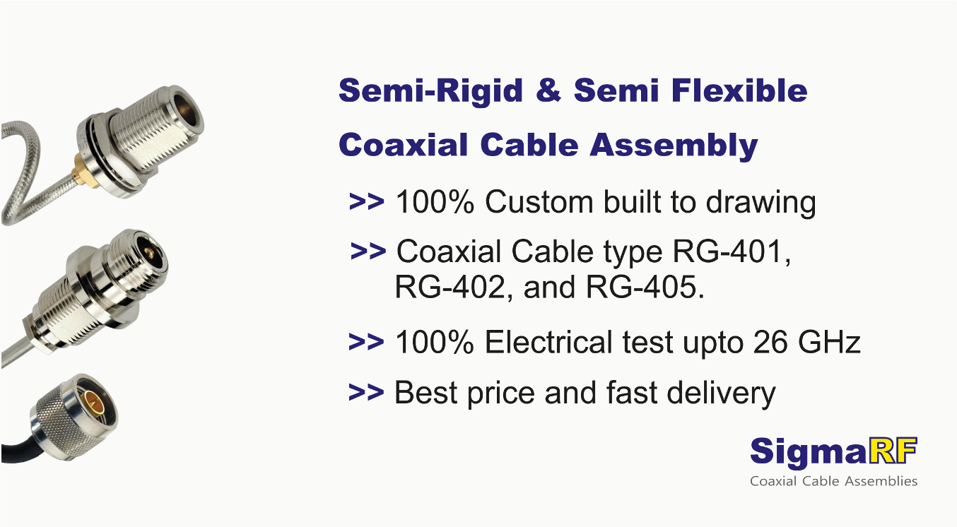
This article covers the semi-rigid families that dominate aerospace and defense work (RG-401, RG-402, RG-405 and their commercial equivalents), the jacket and conductor variations that exist for specific environments, what space qualification actually involves, why matched sets matter for multi-channel systems, and what to look for in a manufacturer when the assembly is going somewhere it can never be repaired.
If you want the general engineering background on semi-rigid construction (why the solid outer conductor outperforms braid, sizes, connector choices, forming rules), we cover that in our complete semi-rigid cable guide. This article assumes that background and goes deeper into the high-reliability side.
On This Page
- Why These Industries Standardized on Semi-Rigid
- The RG-401 / RG-402 / RG-405 Family
- Jacket and Conductor Variations
- Dielectric Options Beyond Standard PTFE
- What Space Qualification Actually Means
- Phase- and Amplitude-Matched Sets
- What Proper Manufacturing Looks Like
- 100% Testing and What Ships with the Assembly
- Application Notes by Platform
- Specifying an Assembly: What to Provide
- Frequently Asked Questions
- Bottom Line
Why These Industries Standardized on Semi-Rigid
Aerospace, defense, and satellite programs converged on semi-rigid decades ago, and the reasons have not changed. Four properties matter more in these industries than anywhere else, and semi-rigid delivers all four simultaneously:
Permanent geometry
Once formed, the cable holds its exact shape through launch vibration, aerodynamic buffeting, and thousands of thermal cycles. The impedance profile it shipped with is the impedance profile it dies with.
Phase stability
20 to 100 ppm/°C typical, which is what makes multi-channel radar, beamforming, and interferometry possible across the operational temperature range.
Shielding above 120 dB
Dense electronics bays put dozens of RF paths within centimeters of each other. The seamless outer conductor keeps channel-to-channel isolation where the system design needs it.
Compactness
Tight, repeatable bends route signal paths through spaces where a flexible cable's bend radius and service loop would never fit.
The trade-off (one-time forming, no field adjustment) is not a drawback in these applications. Nothing in a satellite gets adjusted after integration anyway. The routing is simulated, verified, and frozen long before hardware is built, which is exactly the workflow semi-rigid was made for.
The RG-401 / RG-402 / RG-405 Family
The mil-spec semi-rigid designations you will meet on aerospace drawings come from MIL-DTL-17. Three dominate:
| Designation | OD | Commercial Equivalent | Max Frequency | Loss @ 10 GHz | Typical Role |
|---|---|---|---|---|---|
| RG-405 | 0.086" | UT-085 | 40 GHz | ~1.3 dB/m | Dense module interconnect, instrument internal |
| RG-402 | 0.141" | UT-141 | 33 GHz | ~0.8 dB/m | The aerospace workhorse, radar and avionics |
| RG-401 | 0.250" | UT-250 | 18 GHz | ~0.5 dB/m | High power, low-loss backbone runs |
The standard construction across all three: silver-plated copper center conductor, solid PTFE dielectric, bare or tin-plated copper outer tube, 50 ohm impedance. Beyond these three, the size range runs much wider than most engineers realize: from 0.020" micro semi-rigid for the densest packaging up to 0.500" for specialized high-power work. The 0.047" size (UT-047) has become increasingly important for mmWave modules where even 0.086" is too large to route.
Jacket and Conductor Variations
The standard copper-jacketed cable covers most work, but the aerospace and defense world has driven the development of a full menu of outer conductor and center conductor options, each solving a specific environmental problem.
| Outer Conductor | Available Sizes | Why You'd Choose It |
|---|---|---|
| Copper, silver-plated | 0.020" to 0.500" | Best RF performance, best solderability, the default for most microwave work |
| Copper, tin-plated | 0.020" to 0.500" | Better corrosion resistance than bare copper, easier handling, small loss penalty above 20 GHz |
| Aluminum | 0.047" to 0.325" | Roughly one-third the weight of copper. Spacecraft and airborne platforms where every gram is budgeted. Requires specialized termination technique |
| Stainless steel | 0.034", 0.047", 0.086", 0.141" | High-temperature environments (engine bays, exhaust-adjacent routing), superior mechanical durability, spring-quality stiffness for repeated-insertion probes |
Center conductor options multiply the matrix further. Standard is silver-plated copper. Stainless steel jacketed cables are available with either a stainless center conductor (maximum durability and temperature capability, higher loss) or a copper center inside the stainless jacket (a hybrid that keeps most of the RF performance while gaining the jacket's mechanical properties). The hybrid construction is common in cryogenic and test-probe applications where the cable is repeatedly flexed at the limit of what semi-rigid tolerates.
A note on stainless for cryogenics, since it comes up in quantum computing and deep-space instrument work: stainless steel has much lower thermal conductivity than copper, which matters when the cable passes between temperature stages and you need to limit heat leak into the cold stage. The RF loss penalty is accepted in exchange for the thermal isolation. This niche has grown substantially with the quantum computing industry.
Dielectric Options Beyond Standard PTFE
Solid PTFE is the default dielectric, and for most applications it is the right one. Three variations exist for specific problems:
Low-loss (low-density) PTFE
Expanded or tape-wrapped PTFE with air content lowers the effective dielectric constant, cutting insertion loss by 15 to 30 percent versus solid PTFE and raising velocity of propagation from about 70 percent to 76 to 85 percent. Chosen when the loss budget is tight at high frequency. The trade is mechanical: the softer dielectric makes the cable more sensitive to forming damage and crush.
Phase-stable non-PTFE dielectrics
Standard PTFE has a well-known problem: a crystalline phase transition near room temperature (around 19 °C) that produces a step change in electrical length right in the middle of the operating range of most systems. Phase-critical programs either characterize and calibrate around it, or spec cables built on alternative dielectrics (typically modified fluoropolymers or silicon dioxide) that eliminate the knee entirely. If your system does phase calibration at one temperature and operates at another, ask about this. It is one of the most common sources of unexplained phase drift in precision systems.
Non-50-ohm impedances
Semi-rigid is also manufactured in 75 ohm (broadcast and instrumentation) and custom impedances for matching transformers, delay lines, and specialized instrument internals. If the design calls for a quarter-wave matching section at 35 ohms, semi-rigid at that impedance is buildable.
What Space Qualification Actually Means
"Space-qualified" gets used loosely in marketing. In an actual flight program, it means the assembly and its materials have been verified against a specific set of requirements. The main ones:
- ✓ Outgassing: materials tested per ASTM E595, with total mass loss (TML) under 1.0 percent and collected volatile condensable materials (CVCM) under 0.1 percent. Outgassed volatiles condense on optics and cold surfaces in vacuum, so every polymer in the assembly (dielectric, any jacket, solder flux residue) has to pass.
- ✓ Thermal vacuum cycling: the assembly survives repeated cycles across the mission temperature range (commonly −55 to +125 °C, sometimes wider) in vacuum, with RF performance verified before and after.
- ✓ Random vibration and shock: qualification levels per the launch vehicle environment, typically tested to levels well above what the flight article will see.
- ✓ Materials traceability: full pedigree from raw cable lot through connector lot through solder alloy, documented so any anomaly on orbit can be traced back through the build.
- ✓ Workmanship standards: assembly per the program's workmanship spec (NASA-STD-8739 series or ECSS equivalents for European programs), with certified operators and inspection records.
- ✓ PIND / radiographic screening (some programs): particle impact noise detection or X-ray screening of connectors for loose particles that could migrate in zero gravity.
Not every program needs every item, and NewSpace constellations often run a lighter qualification flow than a flagship science mission. But when a supplier says "space-qualified," the right follow-up question is: qualified to what? Ask for the specific outgassing data, the thermal vacuum test report, and the workmanship standard. A real space-heritage supplier has these on hand.
Semi-Rigid Assemblies Built and Tested In-House
SigmaRF forms RG-401, RG-402, RG-405, and the full UT-series range on in-house tooling, with custom jigs and fixtures produced in our own tool room. Programmable thermo-cycling, VNA sweep on every assembly, and full test plots for return loss, insertion loss, and phase shipped with each unit. Prototype to production volume.
Request a Quote →Phase- and Amplitude-Matched Sets
Multi-channel RF systems (phased-array radar, monopulse trackers, beamforming networks, correlated instrument channels) need the signals in every path to arrive with a known, fixed relationship. That requires the cables in the set to match each other, and there are two dimensions of matching:
Phase matching controls electrical length. Each cable in the set is measured on a VNA against a reference and trimmed until the whole set falls within tolerance. Typical specifications run from ±1 degree at 10 GHz for demanding interferometry to ±10 degrees for routine beamforming work. Tighter tolerance means more measure-trim iterations per cable and higher cost.
Amplitude matching controls insertion loss variation across the set, typically specified as maximum dB spread between the highest-loss and lowest-loss cables (for example, ±0.1 dB across the set at the operating frequency). Amplitude imbalance in a beamforming network distorts the array taper and raises sidelobes, so systems that specify phase matching usually specify amplitude matching alongside it.
What Proper Manufacturing Looks Like
Semi-rigid assembly quality is determined by the factory. The cable itself is a commodity from a handful of mills; what separates a reliable assembly from a marginal one is the forming, termination, and test process it went through. When evaluating a supplier for high-reliability work, these are the capabilities that matter:
In-house tool room
Every formed assembly needs bend dies and check fixtures matched to its geometry. A supplier with in-house jig and fixture capability builds these in days rather than subcontracting them in weeks, which directly cuts prototype lead time and cost. It also means forming quality is controlled by the same organization that owns the RF result.
Precision cable forming equipment
CNC or fixture-guided bending that hits the drawing's dimensions repeatably without ovalizing the tube or displacing the center conductor. Hand bending around a mandrel is acceptable for one-off lab work; it is not acceptable for a production drawing with toleranced bends.
Controlled soldering and clean room capability
Connector termination under controlled conditions, with flux chemistry appropriate to the application and full flux removal verified. Space and medical work adds clean room assembly to control particulates and ionic contamination.
Programmable thermo-cycling chambers
For qualification testing and for phase-versus-temperature characterization. A supplier who can cycle the assembly from −55 to +125 °C while monitoring RF performance can hand you data no datasheet provides: how your specific assembly behaves across your specific temperature profile.
Calibrated VNA test benches
Full S-parameter sweep capability across the assembly's operating band, with calibration traceable to national standards. This is where every assembly proves itself before it ships.
The economic point is worth stating plainly: vertical integration (tooling, forming, termination, and test under one roof) is what makes custom semi-rigid affordable at prototype quantities and fast at production quantities. Suppliers who outsource forming or testing add cost, lead time, and a quality interface at every handoff.
100% Testing and What Ships with the Assembly
For aerospace and defense work, sample testing is not enough. Every assembly is tested, and every assembly ships with its own data. The standard package:
- Return loss plot at both ports across the specified band, against the acceptance limit line
- Insertion loss plot across the band, against the acceptance limit
- Phase data where phase matching or absolute electrical length is specified
- Serial number marked on the assembly and matching the test report
- Certificate of conformance tying the assembly to the drawing revision, cable lot, and connector lots
This documentation is not bureaucratic overhead. When an anomaly appears during system integration two years later, the ability to pull the as-shipped S-parameter data for serial number 0047 and compare it against the current measurement is what separates a one-day diagnosis from a one-month investigation.
Application Notes by Platform
| Platform | What Dominates the Spec | Typical Choices |
|---|---|---|
| Satellite payloads | Outgassing, mass, thermal cycling, no serviceability | RG-405/402, aluminum jacket where mass-critical, full space qual flow |
| Defense radar | Channel isolation, phase match across the array, vibration | RG-402, phase- and amplitude-matched sets, SMP/SMPM terminations |
| Avionics | Vibration, temperature range, weight, long life | RG-402/405, stainless jacket near hot sections, qualified workmanship |
| Electronic warfare | Broadband performance, isolation, density | 0.047" and 0.086" sizes, high-frequency assemblies to 26 GHz and beyond |
| Precision instrumentation | Repeatability, phase stability, calibration traceability | Matched sets, phase-stable dielectrics, characterized thermal behavior |
| Cryogenic / quantum | Heat leak between temperature stages | Stainless jacket with stainless or copper center, small diameters |
Specifying an Assembly: What to Provide
A complete specification lets the manufacturer quote accurately and build right the first time. The checklist:
- ✓ Cable type and size (RG-402, UT-085, or dimensions if custom), including jacket material
- ✓ Connector type and orientation at each end, with plating if it matters
- ✓ Dimensional drawing for formed assemblies: every bend, radius, and toleranced dimension. Point-to-point 3D coordinates work as well
- ✓ Frequency range, maximum insertion loss, minimum return loss across that range
- ✓ Phase or amplitude matching requirements, tolerance, and reference frequency, if applicable
- ✓ Environmental requirements: temperature range, vibration levels, outgassing compliance, any qualification testing
- ✓ Documentation requirements: test plots, C of C, traceability level, first-article inspection
- ✓ Quantity now and projected, since tooling amortization changes the unit economics
If you do not yet have all of this, that is normal at the prototype stage. A capable manufacturer will work from a sketch and a target spec and help converge the drawing. What matters is knowing which requirements are hard and which are preferences, so the design effort goes where it counts.
Frequently Asked Questions
What is the difference between RG-402 and UT-141?
Same cable, different paperwork. RG-402 is the MIL-DTL-17 designation with its qualification and QPL requirements; UT-141 is the commercial designation for the equivalent 0.141" semi-rigid. Dimensions and electrical performance are the same. Defense and flight programs sometimes contractually require QPL-listed cable; commercial and industrial programs generally accept the commercial equivalent with full test data at lower cost. The same relationship holds for RG-405 / UT-085 and RG-401 / UT-250.
Why use aluminum-jacketed semi-rigid cable?
Weight. Aluminum is roughly one-third the density of copper, and on a satellite or airborne platform where mass is budgeted by the gram, swapping copper-jacketed for aluminum-jacketed semi-rigid across dozens of RF paths saves real mass. Available in sizes from 0.047" to 0.325". The trade-off is that aluminum requires specialized termination processes since standard tin-lead soldering does not bond to it directly.
When is stainless steel semi-rigid the right choice?
Three cases. High-temperature routing (engine bays, exhaust-adjacent paths) where copper's temperature limits are exceeded. Mechanically demanding uses (test probes, repeated-insertion fixtures) that exploit stainless spring properties. And cryogenic systems, where stainless steel's low thermal conductivity limits heat leak between temperature stages, an application that has grown rapidly with quantum computing. Available in 0.034", 0.047", 0.086", and 0.141" sizes, with either stainless or copper center conductors.
What does space-qualified mean for a cable assembly?
At minimum: materials pass ASTM E595 outgassing limits (TML under 1.0 percent, CVCM under 0.1 percent), the assembly survives thermal vacuum cycling across the mission temperature range with RF performance verified before and after, vibration and shock qualification to the launch environment, full materials traceability, and assembly per a recognized workmanship standard such as the NASA-STD-8739 series. Always ask a supplier claiming space qualification which specific requirements their product has been verified against.
What is the PTFE phase knee and why does it matter?
PTFE undergoes a crystalline phase transition near 19 °C that causes a step change in its dielectric constant, which shows up as a step in the cable's electrical length right around room temperature. For most systems it is invisible. For phase-critical systems that calibrate at one temperature and operate at another, it produces unexplained phase drift. The fixes are either characterizing the knee and calibrating around it, or specifying cables with phase-stable non-PTFE dielectrics that eliminate the transition.
What is an amplitude-matched cable set?
A set of cables selected or built so their insertion losses fall within a specified spread, for example ±0.1 dB across the set at the operating frequency. Amplitude matching is specified alongside phase matching in beamforming and array systems, because loss imbalance across channels distorts the array's amplitude taper and raises sidelobe levels even when the phases are perfect.
Why does in-house tooling matter when choosing a supplier?
Every formed semi-rigid assembly needs bend dies and inspection fixtures specific to its geometry. A supplier with an in-house tool room builds these in days and controls the forming quality directly, which shortens prototype lead time, cuts tooling cost, and removes a quality handoff. Suppliers who subcontract tooling add weeks to first articles and put a third party between your drawing and your hardware.
What test data should ship with a high-reliability assembly?
Per-serial-number VNA plots for return loss and insertion loss across the specified band against the acceptance limits, phase data where matching is specified, and a certificate of conformance tying the assembly to the drawing revision and the cable and connector lots. One hundred percent testing, not sampling. This data is what enables fast root-cause analysis if an anomaly appears during integration or in service.
Bottom Line
Aerospace, defense, and satellite RF is where semi-rigid cable assembly earns its reputation. The RG-401 / RG-402 / RG-405 family plus the wider 0.020" to 0.500" size range, the jacket options in copper, aluminum, and stainless, the dielectric variants for loss and phase stability, and the matched-set capability together cover essentially every high-reliability interconnect problem these industries produce.
The assemblies themselves are only half the story. The other half is the manufacturer: in-house tooling that compresses prototype cycles, forming equipment that holds the drawing, thermo-cycling and clean room capability for qualification work, and a calibrated VNA between every assembly and the shipping dock. When the hardware is going somewhere it can never be serviced, the discipline behind the build matters as much as the cable inside it.
Specify the requirements honestly, insist on per-unit test data, and order the spares matched at build time. The assembly then does what semi-rigid does best: disappears into the signal path and stays there for the life of the mission.
High-Reliability Semi-Rigid Assemblies from SigmaRF
RG-401, RG-402, RG-405 and the full UT-series range, 0.020" to 0.500", in copper, aluminum, and stainless jackets. High-frequency assemblies to 26 GHz, phase- and amplitude-matched sets, and space-qualified builds. In-house tool room, precision forming, programmable thermo-cycling, and 100 percent VNA testing with plots shipped per serial number. Prototype through production volume.
Standard Assemblies Custom Assemblies Talk to an Engineer- Why Cheap RF Cable Assemblies Fail: Construction Shortcuts and How to Spot Them
- Solving Antenna Range Loss on an IoT Device: A Worked Diagnostic Example
- SMA Mating Cycles: How Many Connections Can an SMA Survive?
- RG58 Attenuation: Datasheet Specs vs Real-World Loss
- VNA Testing for Cable Assemblies: How VSWR and Insertion Loss Verification Works
- How a Custom Coaxial Cable Assembly Is Built, Step by Step
- Cellular Repeater and DAS Cable Selection: In-Building Coverage Guide
- Wi-Fi HaLow (802.11ah): Sub-GHz Wi-Fi and Its Antenna/Cable Needs
- RF Interconnects for Test Labs: Building a Reliable VNA Bench
- Direct-to-Cell Satellite and IoT: What It Means for Ground Hardware