RP-SMA to MHF4 Antenna Pigtail: Connect Your M.2 Wi-Fi or 5G Module to an External Antenna
Published on 9/14/2026 • Updated on 9/16/2026
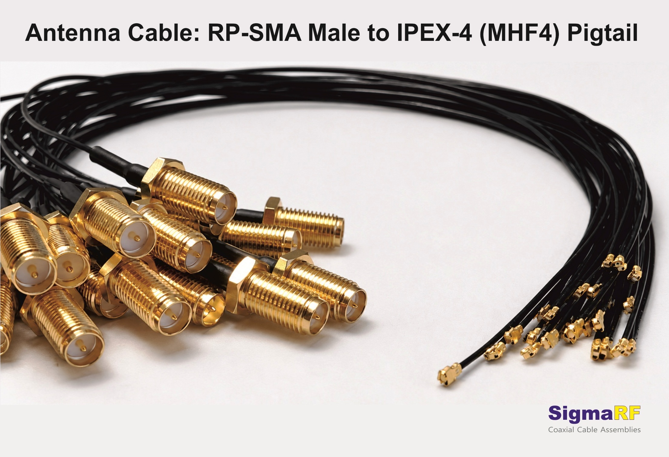
That something is this assembly: an IPEX-4 (MHF4) plug on one end, an RP-SMA male on the other, joined by ultra-flexible 0.81 mm micro-coax. It is one of the most-used RF interconnects in the world right now, riding inside every product built around Wi-Fi 6/6E, Bluetooth, LTE, or 5G M.2 modules from Intel, Qualcomm, Quectel, and others. It is also one of the easiest to get wrong, because every element of it (the connector on the module, the reverse-polarity threaded end, the hair-thin cable) exists for a specific reason, and substituting any of them breaks the design.
This article explains what each part of the assembly does, why the industry converged on exactly this combination, the real numbers behind it, and what to check before you buy one for a production build.
On This Page
- The Problem This Assembly Solves
- The Assembly, End to End
- The IPEX-4 (MHF4) End: Why M.2 Cards Use It
- The RP-SMA Male End: Reverse Polarity Explained
- The RF0.81 Cable: Why This Exact Size
- Typical Specifications
- Insertion Loss and Length: The Numbers
- Applications
- Buying Checklist for Production Use
- Frequently Asked Questions
- Bottom Line
The Problem This Assembly Solves
Three constraints collide inside a compact wireless product, and this pigtail is the industry's answer to all three at once.
The module's connector is tiny and fragile. M.2 wireless cards (2230 and 2242 form factors, including the Intel AX200/AX210 family and most Qualcomm and Quectel modules) carry MHF4 receptacles because there is no board space for anything larger. That receptacle is a precision part rated for roughly 30 mating cycles, and it is soldered to a card you do not want to replace. It must never be the connector that users, installers, or field techs touch.
The enclosure has no room. Inside a mini-PC or a router, the path from the M.2 slot to the enclosure wall threads under cards, past heat sinks, and through gaps a few millimeters wide. Thicker micro-coax (1.13 mm, 1.37 mm, RG-178) fights the routing and, worse, transfers bending strain into the board receptacle. The cable has to be thin enough to route cleanly and flexible enough to place zero load on the module.
The external port has to be robust and deliberately non-standard. The antenna port on the chassis takes the daily abuse: antenna swaps, torque, vibration, the occasional knock. And for Wi-Fi equipment there is a regulatory wrinkle: RP-SMA (reverse polarity SMA) became the Wi-Fi industry's connector precisely because it discourages users from attaching arbitrary high-gain antennas using common standard-SMA parts, in line with the intent of FCC Part 15 rules for unlicensed devices.
When a cheap or wrongly-specified pigtail goes into this role, the symptoms are the familiar ones: weak signal, intermittent drops, high VSWR, and an M.2 receptacle that fails after a handful of insertions. The cure is understanding why each element of the correct assembly is what it is.
The Assembly, End to End
↓
IPEX-4 / MHF4 plug snaps on once at assembly, never touched again
↓
RF0.81 micro-coax, 10 to 30 cm routes under cards and around heat sinks
↓
RP-SMA male bulkhead nut and lock washer clamp it to the chassis panel
↓
External antenna (RP-SMA female)
The design logic will be familiar if you've read our RF cable assembly design guide: the fragile board-level connector is mated once and protected, the chassis-mounted connector absorbs all the mechanical stress, and a short flexible cable isolates one from the other. This pigtail is that architecture in its most-produced form.
The IPEX-4 (MHF4) End: Why M.2 Cards Use It
IPEX-4, MHF4, and "U.FL-4 compatible" all describe the same interface: the fourth-generation micro RF connector from I-PEX, adopted as the de facto standard receptacle on M.2 wireless cards. The previous generation, MHF1 (the original U.FL), served Mini PCIe cards for years, but M.2's tighter real estate demanded something smaller still.
- Footprint about 2.0 × 2.0 mm with a mated height of roughly 1.2 mm, around 40 percent smaller than MHF1. On an M.2 2230 card carrying two antenna ports, that difference is the difference between fitting and not fitting.
- Push-on snap fit with a tactile click. Fast for production assembly, no tools for mating (a proper extraction tool for removal, though; prying with a screwdriver is how pads get lifted).
- Specified for the bands that matter: assemblies built on this interface are typically rated DC to 6 GHz, comfortably covering 2.4, 5, and 6 GHz Wi-Fi plus every sub-6 GHz cellular band. The connector design itself is characterized by I-PEX well beyond that; the 6 GHz assembly rating is the conservative production spec.
- Around 30 mating cycles, which sounds alarming until you remember the design intent: it is mated once at the factory. The repeated-connection duty belongs entirely to the RP-SMA end.
The RP-SMA Male End: Reverse Polarity Explained
RP-SMA trips people up because the naming is genuinely confusing. In a standard SMA pair, the male has outer threads and a center pin. In reverse polarity, the interfaces swap their center contacts: an RP-SMA male has the male's threaded coupling body but a female socket center contact. Its mate, the RP-SMA female found on nearly every consumer and industrial Wi-Fi antenna, has the female threaded body with a male center pin.
The point of the swap is incompatibility. RP-SMA and standard SMA share the same 1/4-36 UNS coupling thread, so the bodies will physically screw together, but the center contacts are then socket-to-socket or pin-to-pin: no connection. Wi-Fi equipment makers adopted RP-SMA in the 1990s so that users could not casually attach arbitrary antennas using ubiquitous standard-SMA hardware, consistent with FCC Part 15's intent for unlicensed transmitters. Two decades later RP-SMA hardware is itself easy to buy, but the convention is now universal across the Wi-Fi ecosystem, so the pigtail must match it.
The rest of the RP-SMA end is standard threaded-connector virtue:
- 50 ohm interface with repeatable contact geometry, rated for 500+ mating cycles: the antenna can be swapped for years without wear becoming a factor
- Threaded coupling holds constant contact pressure through vibration, unlike push-on connectors
- Bulkhead version carries a hex nut and lock washer for panel mounting through a roughly 6.35 mm (1/4 inch) chassis hole, anchoring all antenna torque at the enclosure wall
- Gold-plated center contacts (with nickel- or gold-plated brass bodies) keep contact resistance low and stable across those cycles
- A straight cable-mount version exists for designs where the port is on a flying lead rather than a panel
The RF0.81 Cable: Why This Exact Size
The cable choice here is not a preference; it is dictated by the connector. The MHF4 crimp ferrule is dimensioned for 0.81 mm outer-diameter micro-coax and nothing else. The 1.13 mm and 1.37 mm cables used with MHF1 physically cannot be terminated to an IPEX-4 plug. So every genuine MHF4 pigtail in the world is built on 0.81 mm cable, and the engineering task becomes making that tiny cable perform.
Good RF0.81 construction does exactly that: a silver-plated copper center conductor to fight skin-effect loss, FEP or PFA dielectric for low loss and temperature tolerance, a braided or served shield for flex tolerance, and an FEP jacket. Bend radius is around 4 mm, which is what lets the cable duck under an M.2 card, hug a heat sink, and turn inside a 10 mm gap without complaint or strain on the receptacle.
The honest trade-off: a 0.81 mm cable has a very thin center conductor, and thin conductors mean higher attenuation than 1.13 or 1.37 mm cable. The design response is built into the product convention: keep it short. Standard lengths run 10 to 30 cm, which is enough to reach any enclosure wall while keeping loss to a fraction of a dB. When a design genuinely needs a longer run, the right move is usually a module or antenna relocation, or an MHF1-based assembly on 1.13 or 1.37 mm cable where the module supports it, not a long run of 0.81 mm.
Typical Specifications
| Parameter | Details |
|---|---|
| Impedance | 50 ohm |
| Frequency range | DC to 6 GHz (assembly rating, IPEX-4 interface) |
| VSWR | ≤ 1.3:1 to 3 GHz; ≤ 1.5:1 to 6 GHz |
| Cable | RF0.81 micro-coax, 0.81 mm OD, silver-plated copper conductor, FEP dielectric, braided/served shield, FEP jacket |
| Module-end connector | IPEX-4 / MHF4 plug, gold-plated phosphor bronze contact, ~30 mating cycles |
| Panel-end connector | RP-SMA male, 1/4-36 UNS coupling thread, gold-plated center contact, nickel- or gold-plated brass body, 500+ mating cycles; bulkhead (~6.35 mm panel hole, nut and lock washer) or straight cable-mount |
| Operating temperature | −40 to +85 °C |
| Standard lengths | 10 / 15 / 20 / 30 cm; custom lengths on request |
| Jacket color | Black or grey |
| Testing | VNA sweep for VSWR and insertion loss; batch test reports available for production orders |
Insertion Loss and Length: The Numbers
RF0.81 attenuation per meter, typical values:
| Frequency | Attenuation per Meter | Loss for a 15 cm Pigtail |
|---|---|---|
| 1 GHz | ~1.9 dB/m | ~0.3 dB |
| 2.4 GHz (Wi-Fi, BT) | ~3.2 dB/m | ~0.5 dB |
| 5.8 GHz (Wi-Fi 5/6E) | ~4.9 dB/m | ~0.7 to 0.8 dB |
Read the third column and the length rule writes itself. At 15 cm, the pigtail costs well under a dB even in the 6 GHz band, which any link budget absorbs without noticing. Stretch the same cable to a meter and the 5.8 GHz loss approaches 5 dB, which is the difference between full bars and a flaky link. Choose the shortest length that reaches the panel with comfortable routing slack, and no more.
One more practical note for MIMO: a 2x2 Wi-Fi module has two antenna ports and takes two pigtails. Keep the pair the same length and construction so the chains stay balanced; mismatched pigtails skew the MIMO performance the module's firmware assumes. For the fuller treatment of module-to-antenna design (including MIMO matching and panel-mount styles), see our guide on connecting Wi-Fi modules to external antennas.
RP-SMA to MHF4 Pigtails, Built and Tested by SigmaRF
Standard 10 to 30 cm lengths or custom to your drawing, bulkhead or straight RP-SMA, black or grey jacket, with matched-length sets for MIMO builds. Every assembly VNA-swept for VSWR and insertion loss, with batch test reports available for production orders.
Request a Quote →Applications
Wi-Fi 6/6E in laptops and mini-PCs NAS and embedded boards 4G/5G routers with M.2 cellular modules Drones, robotics, telemetry links Industrial IoT gateways Bluetooth and BLE equipment
The shared profile: an M.2 (or other MHF4-equipped) radio module inside a compact enclosure, an external antenna requirement, and operation in the 2.4 to 6 GHz range where a short 0.81 mm run costs almost nothing.
Buying Checklist for Production Use
- ✓ Confirm MHF4, not MHF1. Check the module datasheet, not a photo. The two generations look alike and do not interchange; M.2 cards are MHF4, older Mini PCIe cards are MHF1.
- ✓ Confirm RP-SMA, not SMA. Look at the antenna you'll mate: if its connector has internal threads with a center pin, it's RP-SMA female and this assembly's RP-SMA male is correct. The threads of SMA and RP-SMA engage each other, so a mismatch fails silently at the center contact rather than obviously at the threads.
- ✓ Choose the shortest length that reaches the panel with a little routing slack. Loss scales directly with length, and excess cable coiled inside a chassis is a pinch hazard at assembly.
- ✓ Specify bulkhead or straight RP-SMA depending on whether the port mounts through a panel or hangs on a lead. Bulkhead is the norm for enclosed products.
- ✓ Order MIMO pigtails as matched sets of identical length and construction, one per antenna port.
- ✓ Ask for VSWR and insertion-loss test reports per batch for production builds. A pigtail is cheap; debugging a thousand marginal ones in the field is not.
- ✓ Train assembly staff on MHF4 handling: press straight down to mate, use the extraction tool to remove, never lever sideways. One side-load can lift the receptacle off the card.
Frequently Asked Questions
What is the difference between IPEX-4, MHF4, and U.FL?
IPEX-4 and MHF4 are two names for the same fourth-generation I-PEX micro RF connector, standard on M.2 wireless cards, terminating 0.81 mm cable. U.FL (also called MHF1 or IPEX-1) is the older, larger first-generation connector used on Mini PCIe cards, terminating 1.13 or 1.32 mm cable. They look similar but are mechanically incompatible; forcing one onto the other's receptacle destroys the receptacle.
What is an RP-SMA male connector?
A reverse-polarity SMA connector with the male's externally-threaded coupling body but a female socket center contact. It mates with the RP-SMA female found on nearly all Wi-Fi antennas. It shares the 1/4-36 UNS thread with standard SMA, so the bodies can screw together, but a standard SMA will not make electrical contact with it: the center contacts end up socket-to-socket. That deliberate incompatibility is why Wi-Fi equipment adopted it.
Can I use 1.13 mm cable with an MHF4 connector?
No. The MHF4 crimp ferrule is dimensioned for 0.81 mm outer-diameter cable only; 1.13 mm and 1.37 mm cable physically cannot be terminated to it. Those larger cables pair with MHF1/U.FL connectors. If your run is long enough that 0.81 mm loss is a problem, the solution is shortening the run or using a module interface that accepts larger cable, not forcing cable onto the wrong connector.
How much signal does an MHF4 pigtail lose at Wi-Fi frequencies?
A 15 cm RF0.81 pigtail loses roughly 0.5 dB at 2.4 GHz and 0.7 to 0.8 dB at 5.8 GHz, small enough that any link budget absorbs it. The per-meter figures (~3.2 dB at 2.4 GHz, ~4.9 dB at 5.8 GHz) explain why these pigtails are kept to 10 to 30 cm: at a full meter the 5 GHz-band loss approaches 5 dB, which visibly hurts throughput.
Why does my Wi-Fi antenna not work with a standard SMA cable?
Almost certainly a polarity mismatch. Wi-Fi antennas use RP-SMA, and a standard SMA connector will thread onto an RP-SMA port (same 1/4-36 thread) without making center-contact connection: pin meets pin or socket meets socket, and no signal flows. Check whether the antenna connector has a center pin inside internal threads (RP-SMA female) and match it with an RP-SMA male on the cable.
How many times can an MHF4 connector be mated?
Around 30 cycles. This is by design: the MHF4 end is meant to be connected once during device assembly and left alone, while all repeated connection duty (antenna swaps, installation, service) happens at the RP-SMA end, which is rated for 500+ cycles. If a workflow requires frequently disconnecting at the module, use the proper extraction tool and press straight down when re-mating; side-loading is what kills receptacles early.
Bottom Line
The RP-SMA male to IPEX-4 pigtail on RF0.81 cable looks like a commodity part, and in volume it is priced like one. But every element of it is load-bearing: MHF4 because that is what M.2 cards carry, and it must be mated once and protected; RP-SMA male because that is what the Wi-Fi antenna ecosystem mates with, and the threaded bulkhead takes all the mechanical duty; 0.81 mm cable because MHF4 accepts nothing else, kept to 10 to 30 cm so its loss stays negligible.
Get those elements right, with clean terminations and per-batch test data behind them, and the pigtail disappears into the product: full signal, stable link, no field returns. Get any of them wrong (MHF1 confused with MHF4, SMA confused with RP-SMA, a meter of 0.81 mm cable, a side-loaded receptacle) and this tiny part becomes the biggest problem in the build. The difference costs nothing but attention at specification time.
RP-SMA to IPEX-4 (MHF4) Assemblies from SigmaRF
Standard lengths of 10, 15, 20, and 30 cm or custom to your specification, bulkhead or straight RP-SMA male, matched sets for MIMO, black or grey jacket. Precision-terminated on genuine RF0.81 micro-coax and individually VNA-tested for VSWR and insertion loss, with batch test reports for production orders.
Standard Assemblies Custom Assemblies Talk to an Engineer- Counterfeit RF Connectors: How Buyers Get Burned and How to Check Provenance
- Outdoor Antenna Cable Assemblies: A Buyer's Spec Guide (IP Ratings, UV, Grounding)
- SMA vs N-Type vs TNC vs BNC: Choosing the Right RF Connector
- Replacing an Obsolete or Unavailable Cable Assembly From a Sample or Spec
- First Article Inspection for Cable Assemblies: What to Require Before Production
- How to Compare Cable Assembly Quotes (and Why the Cheapest One Costs More)
- Custom vs Off-the-Shelf RF Cable Assemblies: Cost, Lead Time and Risk
- Quick-Turn Custom Cable Assemblies: What Lead Time Is Realistic
- How to Qualify an RF Cable Assembly Manufacturer: A 12-Point Audit
- Low MOQ Custom RF Cable Assemblies: Buying Small Lots Without the Runaround